Model IFP-2100/ECS Installation Manual LS10143-001SK-E
4-37
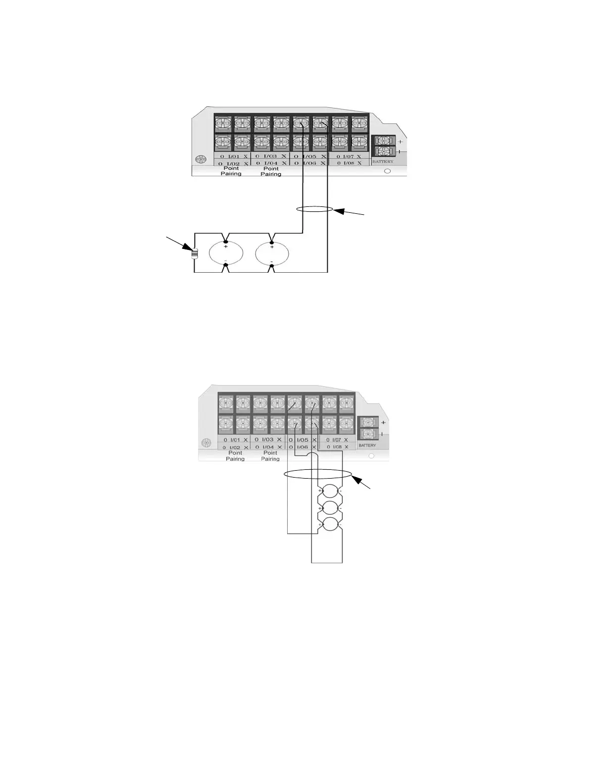
4.15.3.1 Installing 2-Wire Class B Smoke Detectors
To install a Class B two-wire smoke detector, wire as shown in Figure 4-51.
Figure 4-51 Two-Wire Class B Smoke Detector
4.15.3.2 Installing 2-Wire Class A Smoke Detectors
To install a Class A two-wire smoke detector, wire as shown in Figure 4-52.
Figure 4-52 Two-Wire Class A Smoke Detector Connections
Note: In programming any point that uses multiple Flexput circuits, the lowest Flexput circuit number is used to
refer to the circuit pair. For example, Figure 4-52 uses both Flexput circuit 5 and 6, so in programming it
would be referred to as point 5.
4.15.4 Installing 4-Wire Smoke Detectors
Any compatible UL listed four-wire smoke detector can be used with the control panel (see Appendix A for list
of compatible smoke detectors). Figure 4-53 and Figure 4-54 illustrate how to connect a UL listed four-wire
Note:
Flexput circuit 5
used as an example.
Any Flexput circuit
could be used.
EOL 4.7 k Ω
Maximum Impedance per circuit is 50Ω
supervised
power limited
Any 2 wire
smoke detector
listed in Appendix A
Note:
Flexput circuit 5 and 6
used as an example.
Any Flexput point pairing
could be used.
supervised
power limited
Maximum Impedance per circuit is 50Ω
Any 2 wire
smoke detector
listed in
Appendix A

 Loading...


