Model IFP-2100/ECS Installation Manual LS10143-001SK-E
5-5
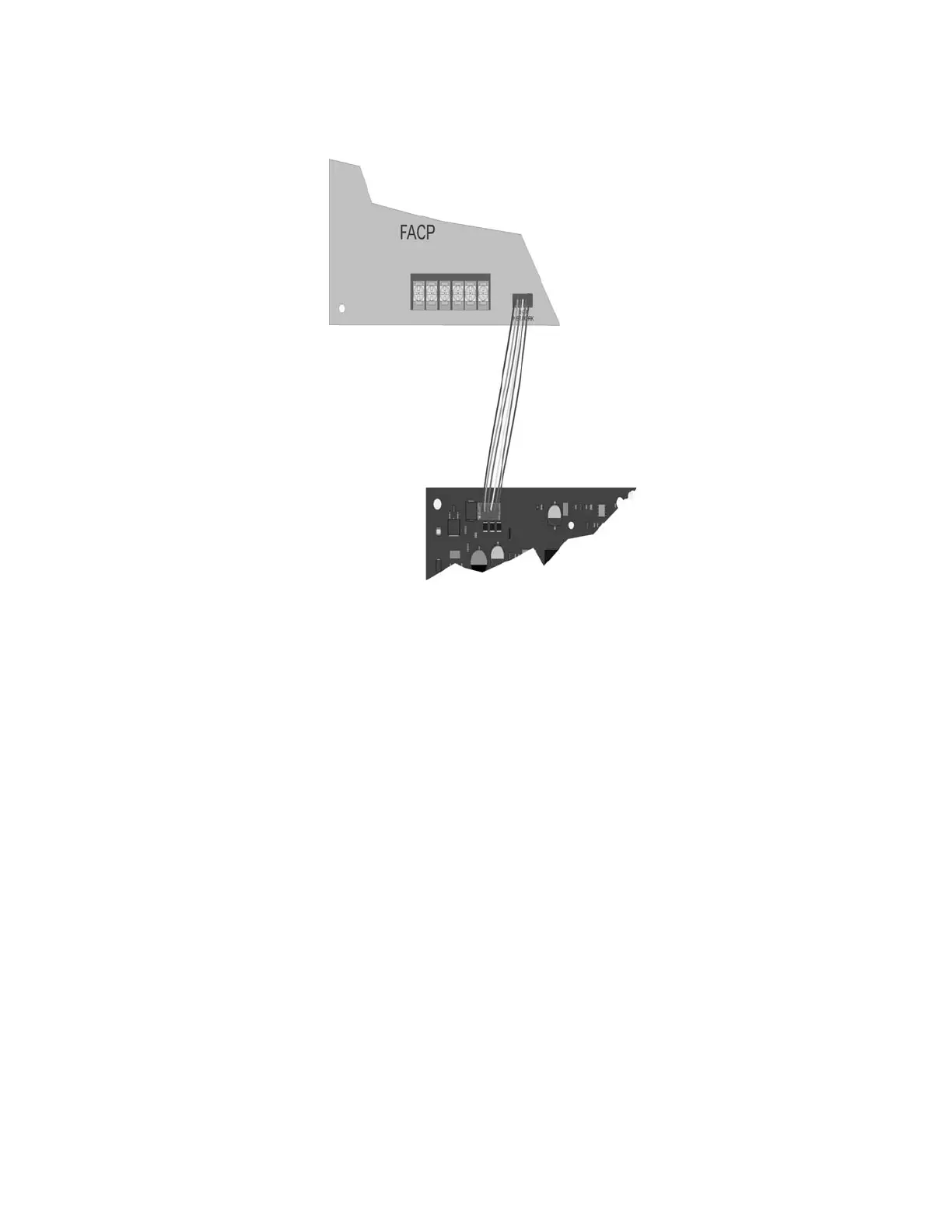
2. Use the 6-pin cable included with SK-NIC to connect the IFP-2100/ECS to the SK-NIC. Connect the SK-
NIC to the pin connector on the control panel labeled Data Network. See Figure 5-6.
Figure 5-6 Panel to SK-NIC connection
3. Each SK-NIC has the ability to monitor for earth ground faults on the twisted pairs connected to Port 1 of its
terminal block TB2. Earth fault detection for any wiring at Port 2 of TB2 is done at the next/previous SK-
NIC due to these wiring connections being connected to Port 1 of TB2 at the next/previous SK-NIC.
4. Unused optic ports on fiber loop modules must have their dust caps placed on the port.
5. Based on the type of data medium chosen, run the twisted pair wiring/fiber optic cable to the next SK-NIC
using a class B or class A wiring method. A combination of both medium types can be used. See Figure 5-7,
Figure 5-8, Figure 5-9, and Figure 5-10 for SK-NIC wiring examples.
To mount the SK-NIC remotely:
Follow the steps above except; The 6-pin cable that runs from the SK-NIC to the IFP-2100/ECS, must be run in
conduit. See Figure 5-1.

 Loading...


