Fire Alarm Control Panel IQ8Control C/M
FB 798951.GB0 / 01.09 89
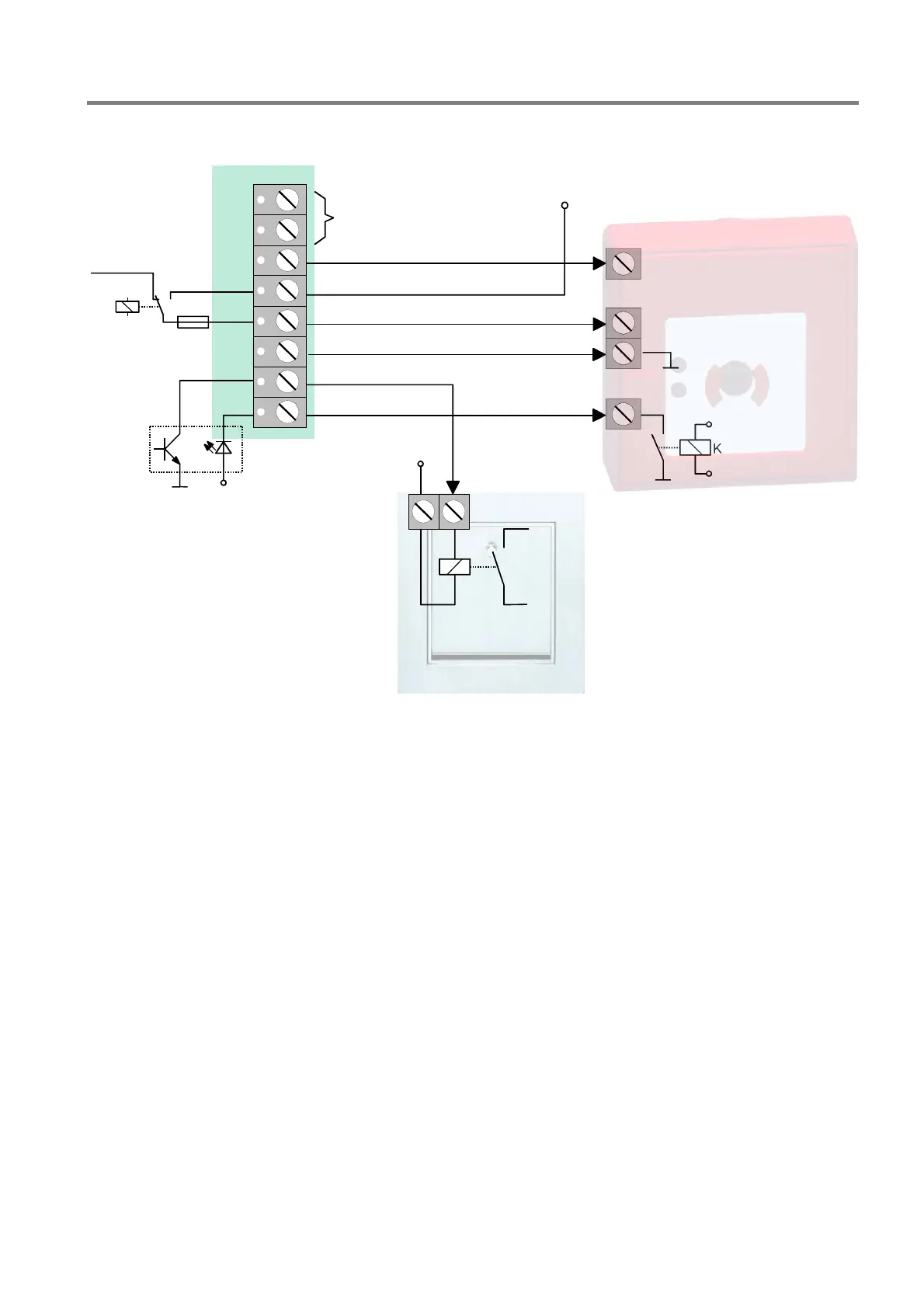
Wiring of the terminal card
F1
GND
+UBext.
1
2
3
4
5
6
7
8
+
K
K
not use
MFAB reset (+12 V or +24 V / 300 mA)
+ MFAB
supply
voltage
primary loop to MFAB (+MFAB)
unlock fire department box (switched to GND max. 300 mA)
MFAB
acknowiedgment
MFAB
(schematic circuit diagram)
MFABrelay
monitoring
FDKB
unlock
fire dept. key box
(schematic circuit diagram)
acknowiedgment
contact
Fig. 78: Wiring of the terminal card
he signal to enable the fire service key box (FDKB) is activated when the master box acknowledge signal
ptical displays of the master box
fied by a steadily lit red LED Main Detector (MFAB) on the control panel of
it has been impossible to activate a master box due to an event, possibly because the MFAB was switched
T
(terminal 8 = MFAB acknowledge) from the Fire Alarm Control Panel is detected.
O
An activated master box can be identi
the Fire Alarm Control Panel. Intervening personnel such as the fire department have been notified.
If
off, this is indicated on the control panel by the steadily lit red LED Notify fire department.

 Loading...


