23
Page 23
Mini-AT User Guide
Installing a Mini-AT without an Instrument Drive
The Mini-AT can be configured to accept low frequency meter input pulses directly from a meter or
Model 210/212 pulse transmitters (or any other low frequency pulse source) if a RSI board is installed.
Alternatively, the Mini-AT
can be configured to accept high frequency pulses from turbine meters input, but
requires the High Frequency Input Board (HFI Board) instead of the RSI board (see Figure 6).
1) Low Frequency Meter Pulse Input
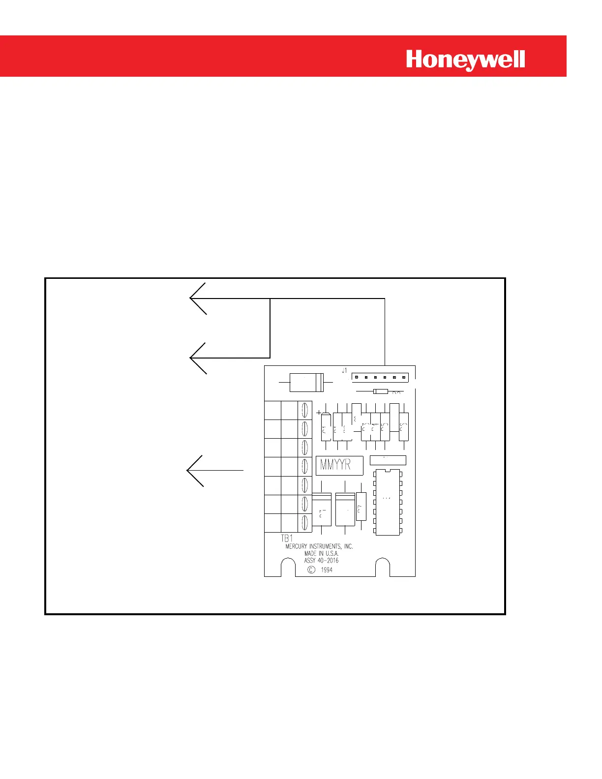
The Remote Switch Interface Board (RSI board, p/n 40-2016), must be installed if the Mini-AT is to
receive input pulses from a Model 210/Model 212 Pulse Transmitter or a low frequency pulse from a
gas meter. Figure 5 (below) and T
able 1 (on the next page) provide wiring information for the RSI and Pulse
Transmitters.
To Mini-AT main
board J9 & J4, use
Y-cable
40-1939
To Model 210 or 212
Pulse
Transmitters,
or pulse output from
gas meter
1 6
TB1
1
2
3
4
5
6
7
Figure 5
RSI Board
(Continued on the next page)
 Loading...


