73
Page 73
Mini-AT User Guide
Main Board Jumpers
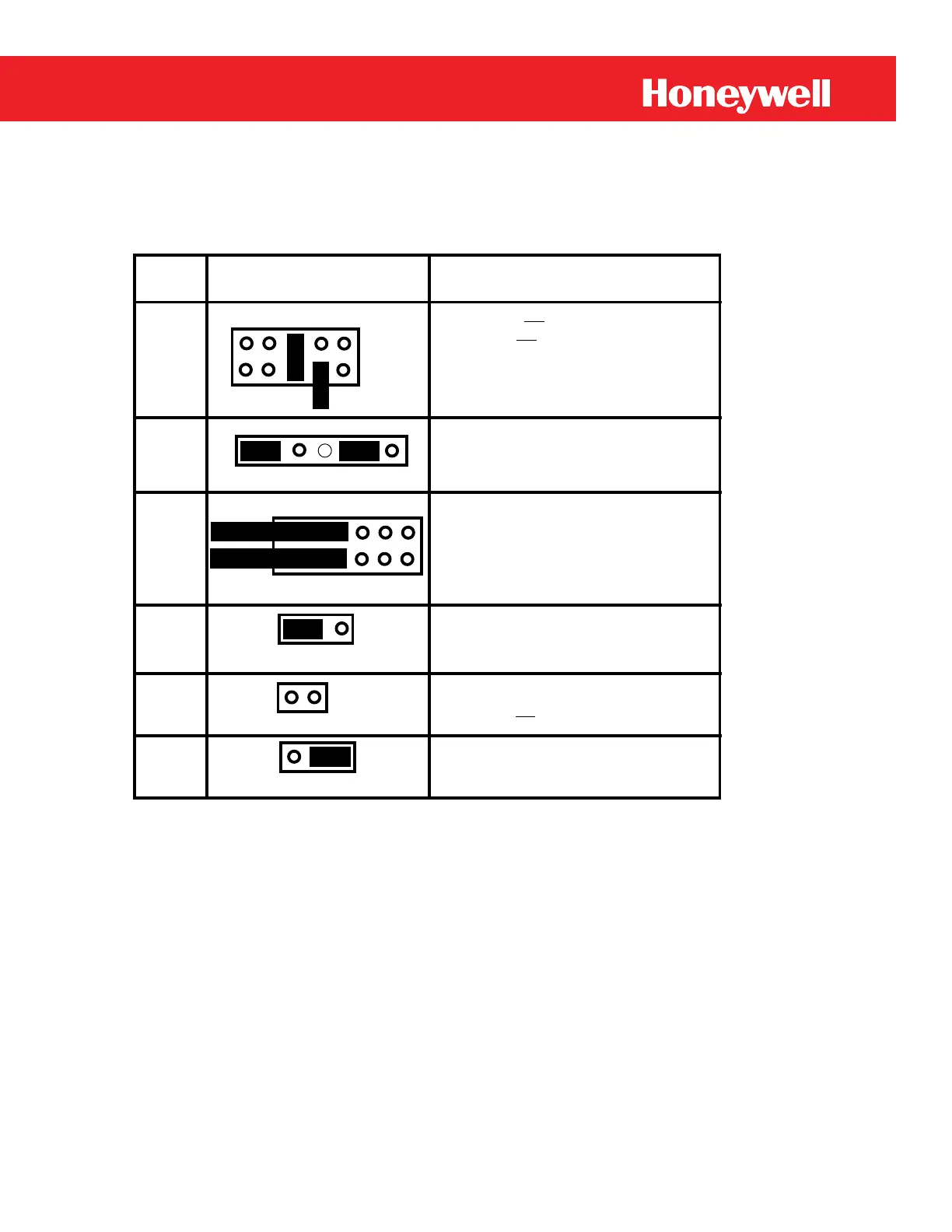
The Mini-AT has several features and functions that are controlled by installing jumpers on header
pins. Table 9 lists all main board jumpers with their factory default settings.
Table 9
Default Jumper Settings
1 3 5 7 9
2 4 6 8 10
JB24
JB29
JB31
1 2 3 4 5 6 7
1 2 3
JB32
1 2
JB900
1 2 3
Jumper Jumper Default
Name Configuration (Default) Purpose
1 2; LOADER not executed after reset,
3 4; Defaults not loaded after unconfigured
5-6; Flash Upgrades permitted
7-8; Serial access limited by the selection
at items 139, 126 and 272
9 10; Prevent setting of Event Log Lock
1 3 5 7 9 11
2 4 6 8 10 12
JB30
2-3; Selects serial data for modem operation
at TB2
Note:1-2; Selects Aux modem operation (J20)
1 2; Current limiting resistor to input switch
board is not bypassed.
1-2; Selects input signal to pulse circuits as
Form-A
Note: 2-3; Selects input as Form-C
1-3-5 and 2-4-6; Configures TB1 for
2 Form-A pulse channels, i.e., KYa and KYb.
Note: 1-3-5-7-9-11 and 2-4-6-8-10-12;
configures TB1 for a single Form-C channel
1-2 (not 2-3) and 5-6 (not 6-7)
Sets pulse width of KYa and KYb to
62.5 milliseconds. (Other pulse widths can be
achieved by substituting shunt resistors)
 Loading...


