3.0 Wiring
Warning
Wiring and testing must be performed by experienced and trained professionals.
For reference, you can find wiring diagrams for the respective boiler in the Appendices on page 93. This
section includes the following topics:
Boiler pump
Thermostats
Load pumps or valves
Sensors
Alarm contacts
External control
Multiple boilers: wiring and networking
Wiring checklist
Note
For a boiler to fire, it needs an "enabler" across the
load such as a zone valve end switch, thermostat
switch, or jumper.
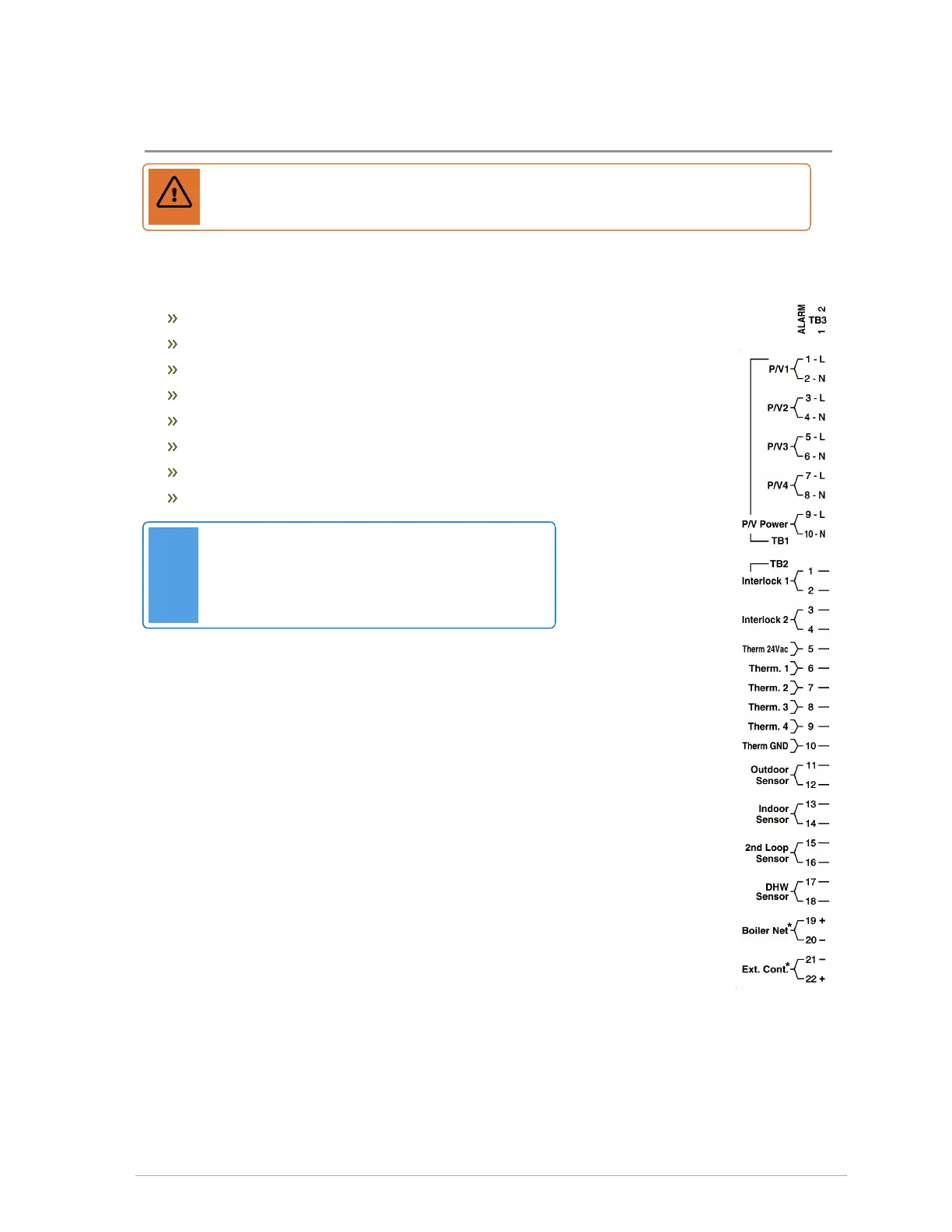
Figure 12 Controller's wiring strip
3.1 Boiler pump
For VX boilers, wire the boiler pump to its boiler pump harness lead. The image
below shows the boiler pump leads (yellow and white wires) located in the wiring
box behind the controller.
 Loading...