3.3 Load pumps or valves
Note that TB1: 9-10 P/V power is prewired with 120VAC.
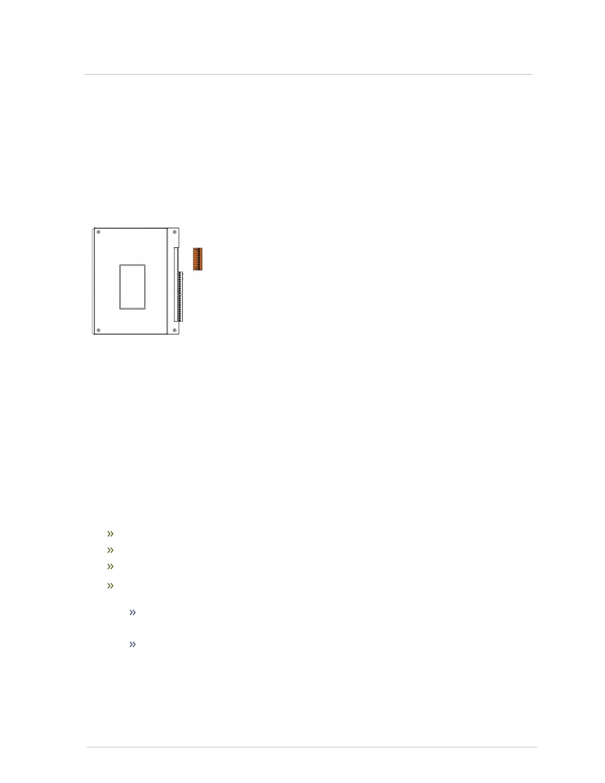
You can wire up to four load pumps to the load pump terminal labeled P/V1 (Pump/Valve1), P/V2,
P/V3, and P/V4 (see Figure 12 ). The top pair PV/V1 - 1 L(live) and 2 N(neutral) is reserved for Load 1,
the second pair PV/V2 - 3 L and 4 N is reserved for Load 2 etc.
Figure 14 Load pump terminal
The factory has pre-wired the terminal to use a 120VAC power supply, but it can be configured for other
voltage uses in the field. Note that the total loads running should not exceed 10 amps.
Note that any pump being directly switched by an IBC control board must draw less than 4 amps.
3.4 Sensors
Use a thermister (10K ohm type 2 sensor) wired to any of the following sensors at TB2:
Outdoor Sensor - 11 and 12 terminals
Indoor Sensor - 13 and 14 terminals
2nd Loop Sensor - 15 and 16 terminals
DHW sensor - You can use two methods for wiring DHW on a boiler controller:
Aquastat: Set up a call for heat for DHW by using an aquastat that is wired to a Therm 1,
2, 3, or 4 connection (see Figure 12 ).
DHW sensor: Use a DHW thermister (10K ohm type-2 sensor) to connect to the "DHW
Sensor" 17 and 18 terminal connections (see Figure 12 ). With this method, the Therm
connection corresponding to the DHW pump is not used.
 Loading...