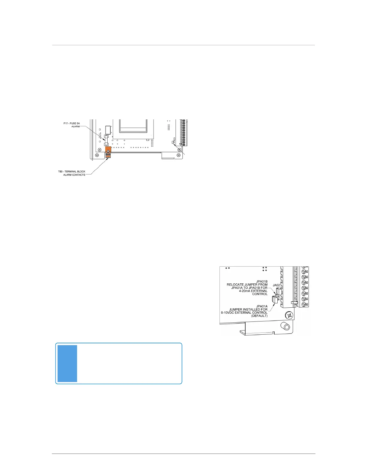
3.5 Alarm contacts
The controller provides a relay dry contact connection to indicate the boiler’s alarm state externally.
This can be used, for example, to connect to an external alarm panel or an indicator light. The
terminals on TB3 (see Figure 12 ) supply the wiring connection. To access the TB3 connection,
disconnect electrical power to the boiler, and remove the controller front cover.
The alarm contacts will normally be open
indicating that there is no alarm present. The
contacts are closed when an alarm state is
present and boiler operation has been
disabled. This corresponds to when the boiler
status bar on the display is red. The error that
was detected creating the alarm state is
recorded in the Error Log and displayed on the
boiler status bar.
Figure 15 Location of alarm contacts on front of controller
3.6 External control
Connections are provided at TB2 Ext. Cont. to receive a 0-10VDC or 4-20 mA signal for throttle
management (see Figure 12 ). The default configuration is 0-10VDC (JPA01A installed).
Note
Always disconnect electrical power to
the boiler before removing the circuit
board cover.
Figure 16 Relocating jumper
 Loading...