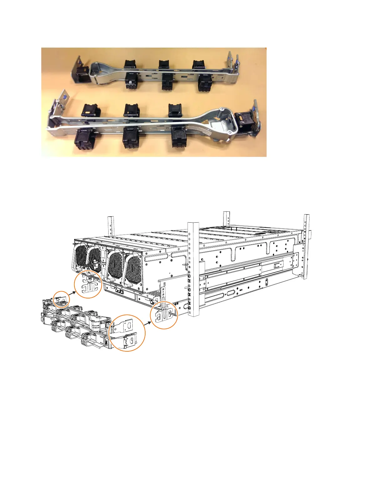
As Figure 69 shows, the support rail connectors of each CMA assembly are
installed on the rail hooks at the end of the support rails.
Procedure
1. Remove the loop straps from the upper and lower CMA assemblies. The straps
are used only for shipping.
Installing the upper CMA assembly
Figure 70 on page 77 shows the connectors on the upper CMA assembly.
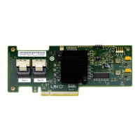
Figure 68. Upper and lower cable-management arms
Figure 69. Upper and lower cable-management arms
76 SAN Volume Controller: Model 2145-SV1 Hardware Installation Guide
 Loading...