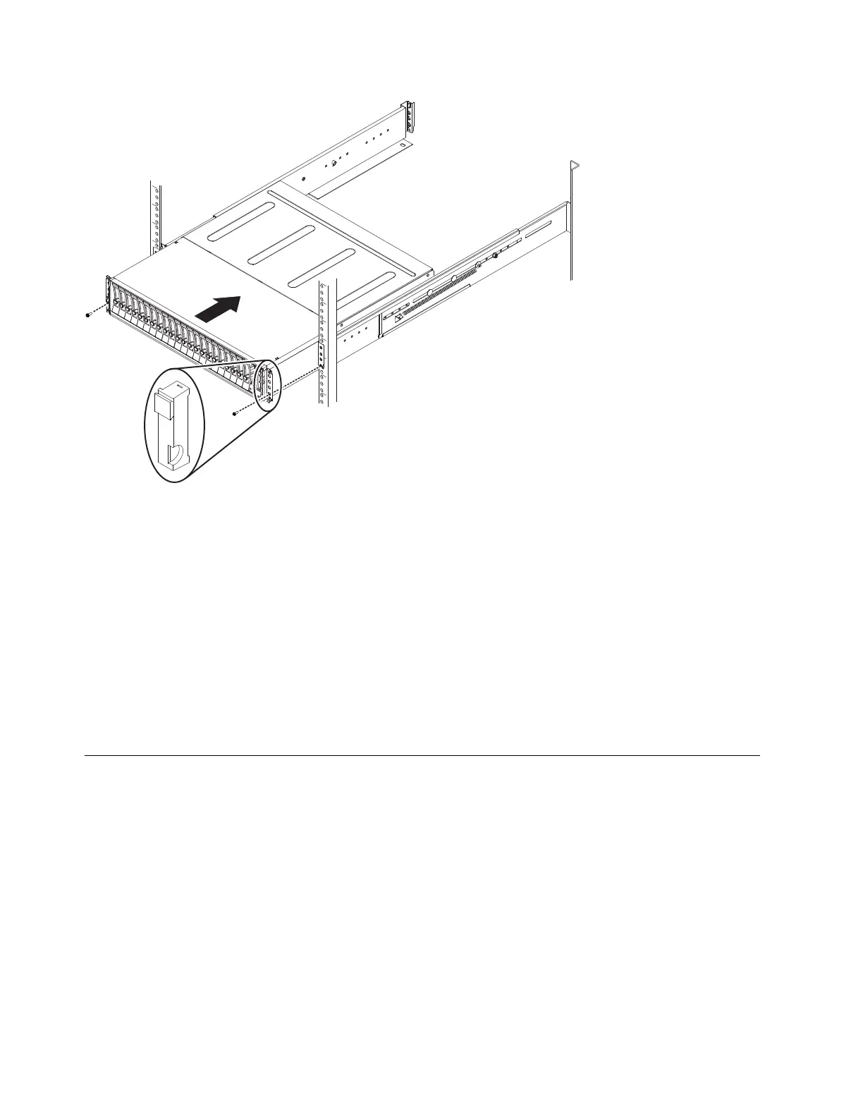
4. Secure the enclosure with screws in the rack mounting screw holes.
5. Reinstall the left and right end caps. See Figure 38. The left end cap has
indicator windows that align with the status LEDs (light-emitting diodes) on
the edge of the enclosure.
a. Ensure that the serial number of the end cap matches the serial number on
the rear of the enclosure.
b. Fit the slot on the top of the end cap over the tab on the chassis flange.
c. Rotate the end cap down until it snaps into place.
d. Ensure that the inside surface of the end cap is flush with the chassis.
6. If you are installing extra SAS expansion enclosures, repeat the previous steps
to complete the installation.
Connecting the optional 2U SAS expansion enclosures to the
2145-SV1
After you install the SAS expansion enclosures into the rack, you must connect
them to each 2145-SV1 node in the IO group that will use them.
About this task
This task applies if you are installing a expansion enclosure. Each pair of nodes in
the system can manage up to 20 expansion enclosures.
Note: When you insert SAS cables, ensure that the connector is oriented correctly.
v When you connect an expansion enclosure, the blue pull tab must be below the
cable (▌1▐ in Figure 39 on page 35).
v When you connect a 2145-SV1, the blue pull tab must be above the connector
(▌2▐ in Figure 39 on page 35).
Figure 38. Inserting the enclosure into the rack
34 SAN Volume Controller: Model 2145-SV1 Hardware Installation Guide
 Loading...