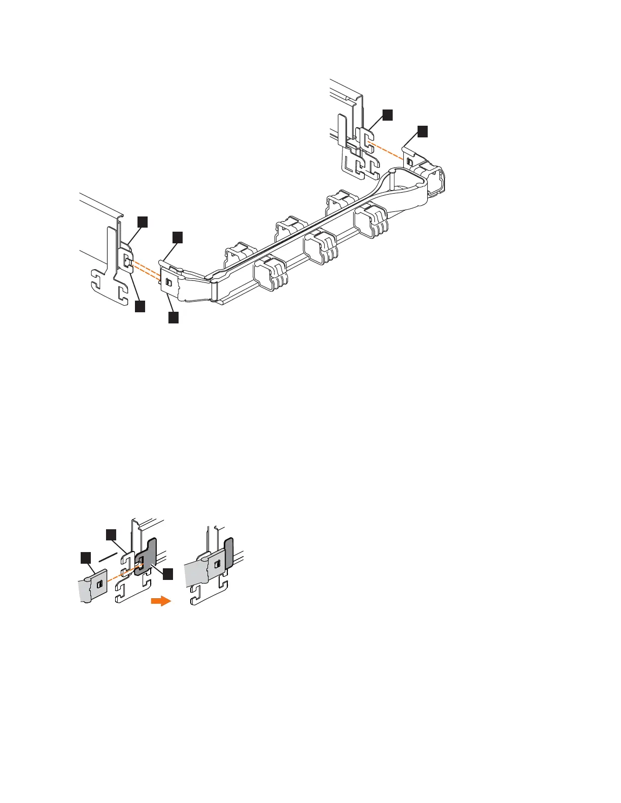
▌1▐ Inner connector on upper CMA
▌2▐ Connector base on inner rail member
▌3▐ Outer connector on upper CMA
▌4▐ Connector base on outer rail member
▌5▐ Support rail connector on upper CMA
▌6▐ Connector base on outer rail member
2. Install the inner connector of the upper CMA assembly (▌1▐) to the inner
member of the left support rail (▌2▐), as shown in Figure 71 from the outer and
inner support rails.
3. Install the inner connector of the upper CMA assembly (▌3▐) to the inner
member of the left support rail (▌4▐), as shown in Figure 72 on page 78.
Figure 70. Connectors for the cable management arm
Figure 71. Install the inner connector of the upper CMA to the inner member of the support rail
Chapter 4. Installing an optional 5U SAS expansion enclosure 77
 Loading...