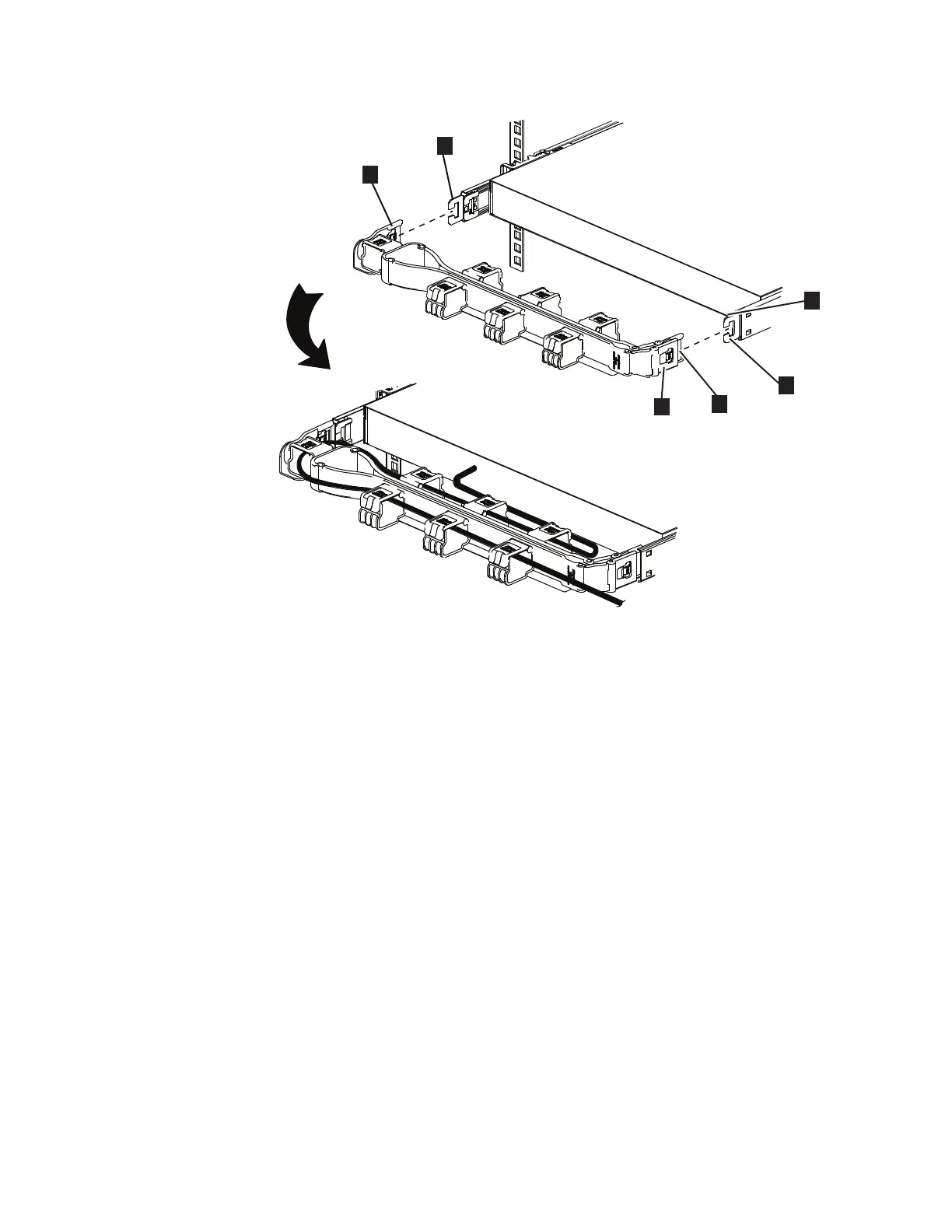
▌1▐ CMA inner connector
▌2▐ CMA connector base on inner member
▌3▐ CMA outer connector
▌4▐ CMA connector base on outer member
▌5▐ CMA connector beside the center body
▌6▐ CMA connector base on outer member
CAUTION:
The loop strap must be tied to the CMA crossbar for transportation. Remove the
loop strap after the system arrives at its final destination.
Procedure
To install the CMA assembly, complete the following steps.
1. Optional: You might need to reverse the left-right orientation of the CMA to
accommodate the routing of cables that lead to the node. To reverse the
orientation of the arm, complete the following steps:
a. Press the button marked "PUSH" in Figure 24 on page 24.
Figure 23. Parts for installing the SAN Volume Controller 2145-SV1 CMA assembly
Chapter 2. Installing the SAN Volume Controller 2145-SV1 hardware 23
 Loading...