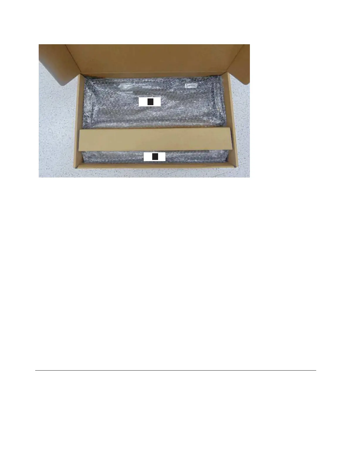
▌1▐ 4U fascia (front)
▌2▐ 1U fascia (power supply units)
12. Attach the 4U and 1U fascia to the front of the enclosure, as described in
“Installing or replacing the fascia: 2145-92F” on page 89.
13. Install the drives, as described in “Installing or replacing a drive: 2145-92F” on
page 81.
14. Replace the top cover, as described in “Installing or replacing the top cover:
2145-92F” on page 80.
15. Lower the mechanical lift so that you can remove the remaining foam blocks
away from the expansion enclosure.
16. Slide the latch on the side of each rail and push the expansion enclosure
securely into the rack, as described in steps 6 on page 68 through 8 on page
68 in “Installing or replacing an expansion enclosure in a rack: 2145-92F” on
page 61.
17. Remove the cable management arm assembly from its packaging (▌2▐ in
Figure 46 on page 54).
18. Attach the cable management arm, as described in “Installing or replacing the
cable-management arm: 2145-92F” on page 75.
19. Connect the SAS cables, as described in “Removing and installing a SAS cable:
2145-92F” on page 97.
20. Connect the power cables.
Removing the top cover: 2145-92F
To perform service tasks, you might need to remove the top cover from a 2145-92F
expansion enclosure.
Figure 48. Packaging for fascia
56 SAN Volume Controller: Model 2145-SV1 Hardware Installation Guide
 Loading...