-101-
Introduction
%"
DPOWFSUFS
7
7
7
%$%$
DPOWFSUFS
'JMUFS
7%$
FYUFSOBMQPXFS
7
$0.
*
7*
.PUPSESJWFNPEVMF
BOEPUIFST
Ē
UP
Ē
'(
"(/%
"(/%
7
Figure 5-45 Connection for current-controlled signal
◆
*1 Use 2-core shielded twisted pair cable as power cable.
◆
*2 If noises or ripples are generated in external wiring
,
connect a capacitor of 0.1 to 0.47 mF 25 V
between terminals V+/I+ and VI-.
3) Wiring instructions
■
Do not bind the cable together with AC cable
,
main lines
,
high voltage cable and so forth; otherwise
,
increased noise
,
surge
,
and induction may be caused.
■
Apply single-point grounding for the shielding of shielded cable and solder sealed cable.
■
Tubed and solderless crimp terminal cannot be used with terminal block. Using marking sleeve or
insulation sleeve to cover the cable connector part of the crimp terminals is recommended.
5.6.5 Temperature Module
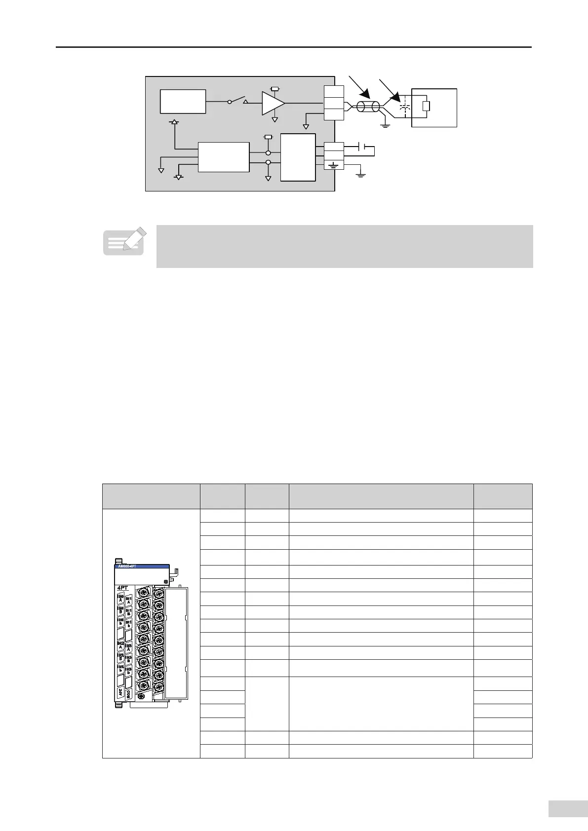
1 Terminal arrangement and signal denitions of the temperature module (AM600-4PT)
1) Terminal arrangement and signal denitions
Terminal Arrangement
Terminal
Symbol
Type Function Terminal No.
IN0 A Input Temperature measuring resistor A of channel 0 1
IN0 B Input Temperature measuring resistor B of channel 0 3
IN0 b Input Temperature measuring resistor b of channel 0 5
IN1 A Input Temperature measuring resistor A of channel 1 2
IN1 B Input Temperature measuring resistor B of channel 1 4
IN1 b Input Temperature measuring resistor b of channel 1 6
IN2 A Input Temperature measuring resistor A of channel 2 9
IN2 B Input Temperature measuring resistor B of channel 2 11
IN2 b Input Temperature measuring resistor b of channel 2 13
IN3 A Input Temperature measuring resistor A of channel 3 10
IN3 B Input Temperature measuring resistor B of channel 3 12
IN3 b Input Temperature measuring resistor b of channel 3 14
NC
Reserved Reserved
7
NC 8
NC 15
NC 16
24 V Power +24 V power supply 17
COM Power 24 V power ground 18
 Loading...


