-80-
Introduction
■
Technical requirements
No short circuit
,
circuit break
,
misplacement
,
or poor contact is detected in the 100% conduction test;
The cable length is within the allowable tolerance range;
The EtherCAT bus transfers network data through a shielded cable. The following table lists the cable
specications:
Item Specications
Cable type Elastic crossover cable
,
S-FTP
,
Cat5e
Standards
EIA/TIA568A
,
EN50173
,
ISO/IEC11801
EIA/TI Abulletin TSB
,
and EIA/TIA SB40-A&TSB36
Wire section AWG26
Wire type Twisted pair
Number of pairs 4
5.5.3 Connection Through the Probus-DP Bus
1 Probus-DP bus specications
Item Specications
Protocol DPV0 and DPV1 (being developed)
Number of slave stations 124 (add a Probus-DP relay every 32 stations)
Communication rate 9.6 Kbit/s
,
19.2 Kbit/s
,
45.45 Kbit/s
,
93.75 Kbit/s
,
187.5 Kbit/s
,
500 Kbit/s
,
1.5 Mbit/s
,
3 Mbit/s
,
6 Mbit/s
,
and 12 Mbit/s
Communication data
volume of a single slave
station
244 bytes/slave
Total data volume of
network communication
5712 bytes/input; 5760 bytes/output
Basic functions Initial state
,
parameter setting state
,
and data exchange state
Special function
Diagnosis. For details
,
see
"7.2 Indicators and MFK Button"
.
Error indicator
SF and BF. For details
,
see
"7.2 Indicators and MFK Button"
.
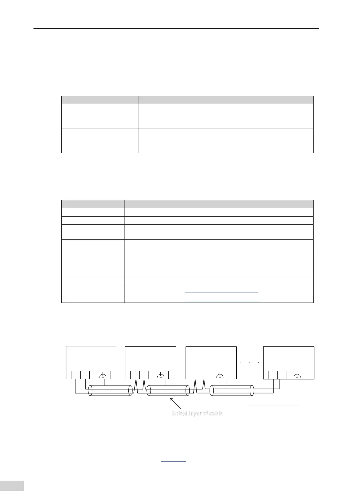
2 Networking diagram
The following gure shows the wiring between the Probus-DP slave station and the Probus master
station:
Profibus-DP
master station
A B
Profibus-DP
slave station 1
A B
Profibus-DP
slave station 2
A B
Shield layer of cable
Profibus-DP
slave station N
A B
Figure 5-21 Network connections
A termination resistors is required for the Probus-DP communication bus. The standard Probus-DP
DB9 connector has already a inbuilt termination resistors
,
and you only need to set DIP witch to enable
the termination resistor. For details
,
see
Figure 5-25
.The system PE must be securely grounded.
The length of the communication cable between the Probus-DP card and the Probus master station
 Loading...


