-77-
Introduction
◆
Note: The preceding gure shows the pin denitions and wiring of the high-density port of the
AM600/610 CPU module. Read it carefully before performing wiring.
5.5 Communication Wiring of the CPU Module
5.5.1 Cable Connection Requirements
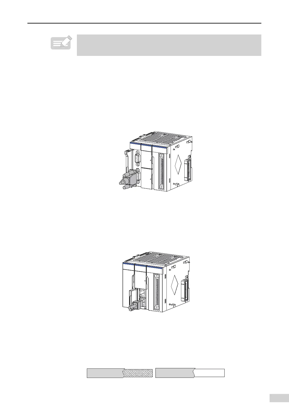
1) Connecting the DB9 connector
2) Plug the DB9 connector (with a cable) to the DB9 plug of the module. (Ensure that the connector
direction is correct.)
3) Tighten the screws on the two sides of the DB9 connector.
Figure 5-15 Connecting the DB9 connector
4) Removal procedure: Unscrew the screws on the two sides of the DB9 connector
,
hold the plastic
part of the connector
,
and pull it out horizontally.
5) Connecting the RJ45 cable
6) Hold the RJ45 connector (with a cable) and insert it to the RJ45 socket of the communication
module until it clicks.
Figure 5-16 Connecting the network cable
7) Removal procedure: Hold the tail of the RJ45 connector and pull it out horizontally.
8) Ethernet cable requirement
Cat5e shielded twisted pair cable with steel-shell molding wires
Figure 5-17 Ethernet cable requirementCommunication cable xing requirement
 Loading...


