-84-
Introduction
Transmission Rate Theoretic Transmission Distance (m)
Actual Reachable Maximum Transmission
Distance (m)
9.6 Kbps to 93.75 Kbps 1000 600
187.5 Kbps 800 480
500 Kbps 400 320
1.5 Mbps 200 160
12 Mbps 100 60
5.5.4 Connection Through the CANopen/CANlink Bus
■
Networking diagram
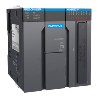
The following gure shows the topological structure of the CAN bus connection. You are advised to use a
shielded twisted pair for CAN bus connection and connect two 120 Ω termination resistors at both ends
of the bus to avoid signal reection. Generally
,
the shield layer uses single point grounding.
CANH
CANL
Set the termination
resistor through switch
1 and 2 of the DIP
switch
CGND
CANL
AM600
CANH
CANL CGND
CANH
CGND
CGND
termination
resistor
120Ω
termination
resistor
120Ω
CANH
CANL
CANlink bus
24V
24 V power
Master station
Slave station 1
Slave station N
DIP switch
DIP switch
Used to set the
termination resistor
on the network
terminal
Figure 5-26 CANopen/CANlink communication connection
■
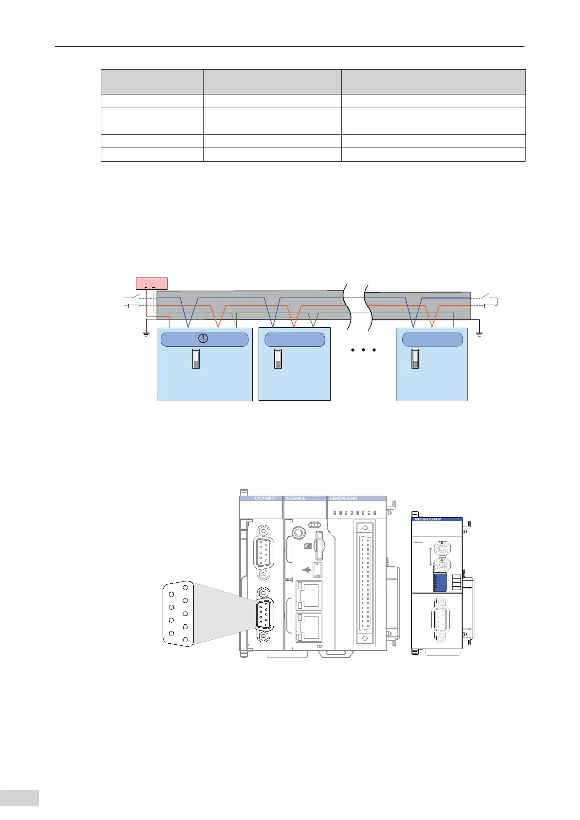
Communication port introduction
CN2 of the CPU module is the CANopen communication terminal and uses a DB9 connector for data
transmission.
RUN
ERR
SF
II
I
0 1 2 3 7654
30 1 4 5 6 72
4 5 6 73210
BF
CANRUN
CANERR
RUN STOP
CN4 EtherCATCN3 EtherNET
CN2 CANCN1 RS485
CN5
12
40 39
MFK
5
4
1
2
3
9
8
7
6
CANERR
CANRUN
POWER
BF
SF
X1
ADDRESS
X16
BAUD
CANOpen
BR2
BR1
R
BR0
COP
Figure 5-27 CANopen terminal denitions of the CPU module
 Loading...


