-57-
Introduction
4.2 Installation Method
4.2.1 Module Installation Process
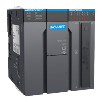
Perform the following steps to install the module:
Mount the DIN guide rail to the installation plane in the
control cabinet
Preparations
Connect the power, CPU, and expansion modules
Install the system protection component (tail board )
Finish
Install the connected module group to the guide rail
Figure 4-2 Installation procedure
4.2.2 Mounting the DIN Guide Rail to the Installation Plane in the Control Cabinet
You can prepare installation guide rails according to the DIN guide rail models (IEC 60715) in the
following table:
Model Length x Depth (mm) Bolt Specications
TH35-7.5Fe 35 × 7.5 M4
TH35-7.5Al 35 × 7.5 M4
TH35-15Fe 35 × 15 M4
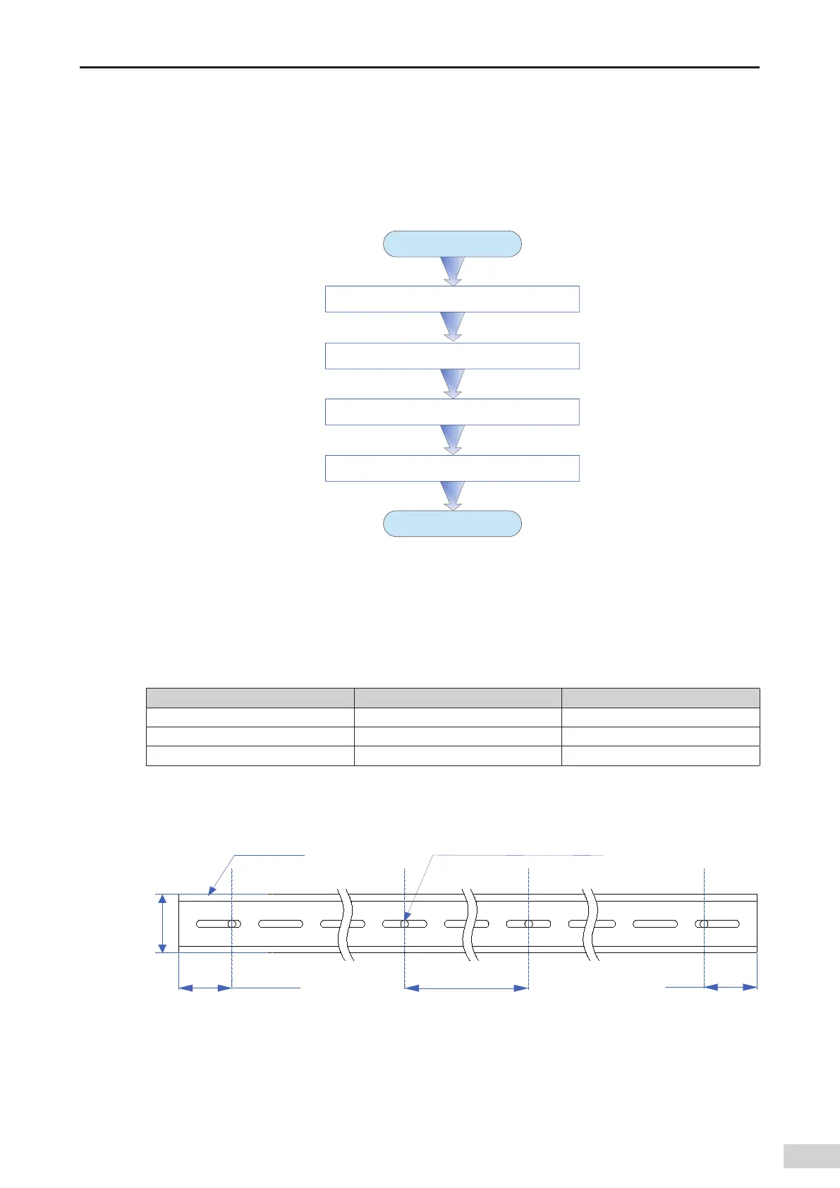
To ensure DIN guide rail strength
,
fasten the installation bolts (prepared by the user) at an interval within
200 mm
,
starting from less than 30 mm from the guide rail end.
≤
%*/
HVJEFSBJM
%*/HVJEFSBJMJOTUBMMBUJPO
CPMUQSFQBSFECZVTFS
≤ ≤
Figure 4-3 Bolt position requirements for DIN guide rail installation (mm)
 Loading...


