-78-
Introduction
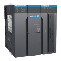
To prevent communication cables from being aected by other tension and ensure communication
stability
,
x the cables on the device side before EtherCAT
,
CANopen
,
or Probus-DP communication
starts
,
as shown in the following gure:
POWER
AM600
Risk of electric shock
EtherCAT
OUTIN
SF
BF
POWER
RUN
ECT
MFK
3940
2 1
CN5
CN1 RS 485 CN2 CAN
CN3 EtherNET CN4 Ether CAT
STOPRUN
CANERR
CANRUN
BF
SF
ERR
RUN
0 1 2 3 7654
2 765410 3
4 5 6 73210
I
II
POWER
AM600
Risk of electric shock
Fix with cable ties
EtherCAT
communication module
小心触电
小心触电
Figure 5-18 Fixing the communication cable on the device side
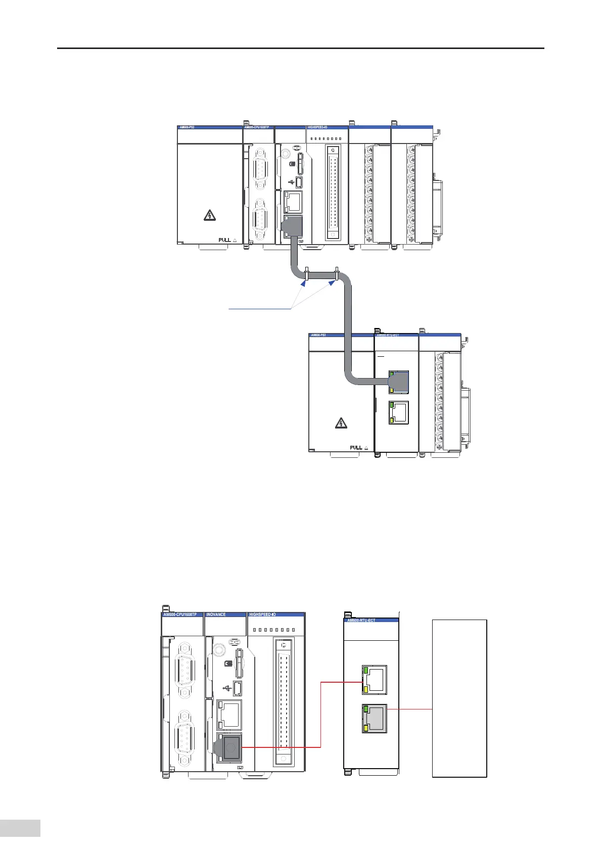
5.5.2 Connection Through the EtherCAT Bus
1 Communication ports
Connect the ports of the CPU module and EtherCAT communication module according to the following
gure.
MFK
3940
2 1
CN5
CN1 RS485 CN2 CA N
CN3 EtherNET CN4 Ether CAT
STOPRUN
CANERR
CANRUN
BF
SF
ERR
RUN
0 1 2 3 7654
2 765410 3
4 5 6 73210
I
II
EtherCAT
OUTIN
SF
BF
POWER
RUN
Next
module
Figure 5-19 CN4 port of the main CPU module and IN/OUT ports of the EtherCAT communication module
 Loading...


