-51-
Introduction
3.6 Remote Expansion Module (Probus-DP)
1) Basic specications
Item Specications
Power supply voltage
24 VDC (20.4 VDC to 28.8 VDC) (–15% to +20%)
,
which can be connected from an
external power supply.
Output current of the internal 5
V power supply
1200 mA (rated)
Protocol for communication
with CPU module
Probus-DP
Maximum baud rate: 12 Mbps
Probus-DP communication
baud rate
9.6 Kbps to 12 Mbps. The speed automatically adapts to that of the Probus-DP
master station.
Station number range
The Probus-DP station number ranges from 1 to 125, but you can only use 31
numbers in the range. You can use the DIP switch to set the station number.
Expandability of subsequent I/
O expansion modules
A maximum of 16 I/O expansion modules can be connected. The number and
conguration vary depending on power consumption of the modules.
Probus-DP Network port One DB9 female connector interface
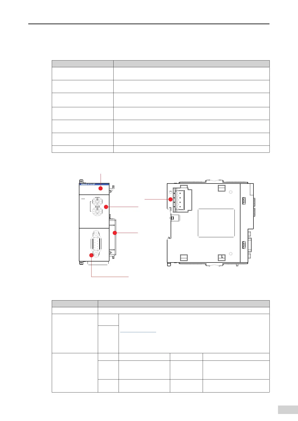
2) Module interface description
SF
BF
POWER
RUN
Profibus-DP
ADD RESS
X16
X
1
24 V
5 V
GND
GND
DP
Signal indicator
DB9 interface
(female connector)
Local
expansion
back-end
interface
Address switch (rotary)
Internal 24 V
power input
terminal
Figure 3-30 Probus-DP module interfaces
Interface Name Function
DB9 interface Probus-DP communication port
Address switch (rotary
switch)
ADDR1
The station address is set with a 16-bit DIP switch. Decimal slave station address
= ADDR1 x 16 + ADDR0 (address range: 1 to 125). For details about the use
,
see
"Chapter 5 Wiring"
.
Note: The number of values that a DIP switch can set is 153 (9 x 16 + 9 x 1). The
Probus-DP station number range is 1 to 125. Therefore
,
you need to avoid
using station numbers greater than 125.
ADDR0
Signal indicators
POWER Power indicator Green On when the power is switched on
SF
Slave station congura-
tion error indicator
Red
On when a conguration error of
the slave station expansion mod-
ule occurs
BF
Slave station expansion
bus error indicator
Red
Blinks when an error of the slave
station expansion bus occurs
 Loading...


