1 Product Information
-
12
-
1
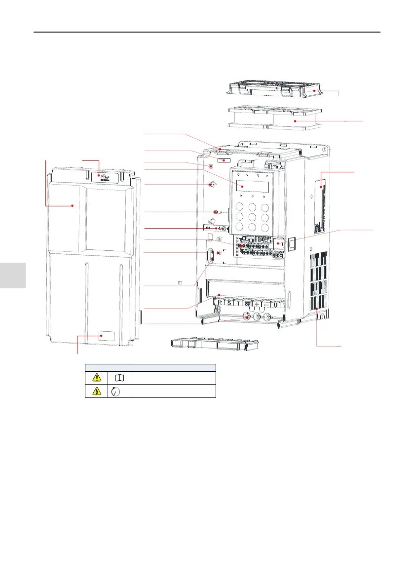
1.2 Description of Parts
The drive can have either a plastic housing or a sheet metal housing, depending on the voltage and power rat-
ing, as shown in the following gures:
Description
i
10min
CAUTION! Read the user guide of the AC drive
carefully before installation or operation.
Warning label
Live indicator
Do not remove/install the drive
when this indicator is lighting
Housing
Cable support bracket
Main circuit terminals
See section 3.2.2
EMC and VDR screw
Refer to Power Grid System in
Section 3.2.2 and requirement
on current leakage in A.6 in
MD500 Series General-Purpose
AC Drive User Manual
Front cover
For removal of the front
cover, see section 3.1.5
Logo
Control circuit terminals
See section 3.2.4
Ground bar
Ground the PG card and
control board
Fixing pin of extension card
See Appendix A Optional Cards
Fixing pin of extension
encoder card
See Appendix A Optional Cards
Operating panel, See section 4.2
Cabling tray and fixing pin of
ground cable of control board
This ground cable can only be
connected to the ground bar after
the system is grounded reliably.
Barcode (0.4~11kW)
View the serial number and
model of the drive here.
Fan cover
Warning label
Nameplate
See section 1.1
Cooling fan
For replacement,
see section 7.3
Interface of external
operating panel
See section 4.3
Barcode (15kW)
View the serial number and
model of the drive here.
Grounding terminal
See section 3.2.2
DANGER! Do not remove the front cover while the
power is on or within10 minutes after the power is
turned off.
Figure 1-2 Schematic diagram of product parts (three-phase, 380V - 480V, MD500T0.4GB to MD500T15GB)