Appendix A
-
138
-
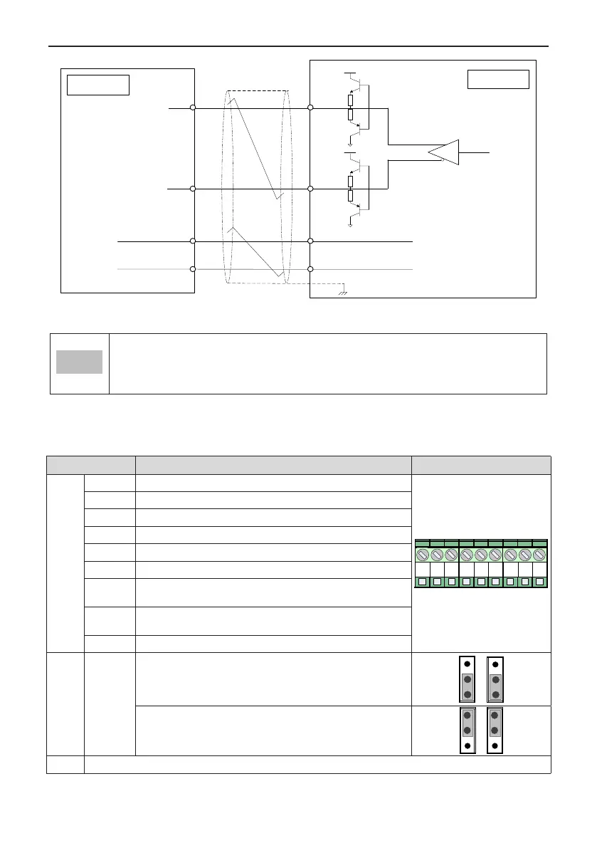
EXC
EXC1
15V
15V
SIN+/COS+
SIN-/COS-
SIN/COS
SINL0/COSL0
PE
Twisted
pair
Twisted
pair
EXC+
EXC-
PG card
Encoder
Figure A-6 Port circuit of D38PG4
● Especially excited input DC resistance must be larger than 17 Ω (can be measured by a multimeter).
Otherwise, MD38PG4 cannot work normally.
● It is suggested to select a resolver with a maximum of four pole-pairs. Otherwise, MD38PG4 will be
overloaded.
A.5.5 Extension Open-collector PG Card (MD38PG5 and MD38PG5D)
Table A-14 Terminal descriptions of MD38PG5 and MD38PG5D
Terminal Function Description Terminal Arrangement
CN2
A Encoder output signal A
J3
A B Z
15V CCM COM
B1 PE
A1
B Encoder output signal B
Z Encoder output signal Z
15V Encoder 15V/100mA power supply
COM Power ground and frequency dividing output ground
COM Power ground and frequency dividing output ground
A1
PG card frequency dividing output signal A (OC output, 0 to 24 V,
0 to 50 mA)
B1
PG card frequency dividing output signal B (OC output, 0 to 24 V,
0 to 50 mA)
PE Shield connecting point
CN3
CN4
"pulse +
direction"
function
Supporting the "pulse + direction" function
Pulse signal connected to phase A, direction signal connected to
phase B
CN3 CN4
Not supporting the "pulse + direction" function (default setting)
CN3 CN4
CN1 18-pin FFC interface, connecting to J4 on the control board of the AC drive

 Loading...