Appendix A
-
130
-
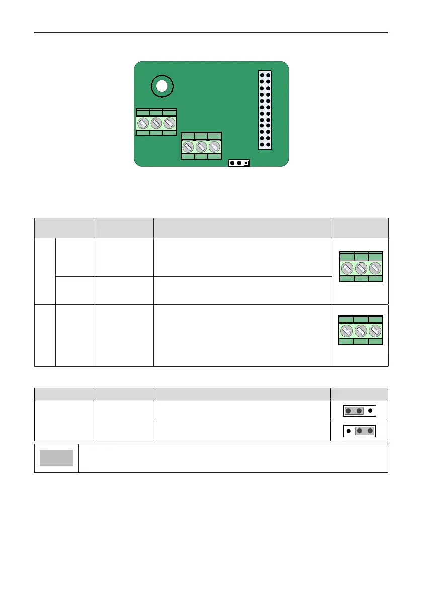
A.4 Layout and Function of Terminals of MD38IO2
DI6 DI7 DI8
J2
COM OP2 +24V
CN1
CN2
Figure A-4 Layout of MD38IO2 terminals
Table A-6 Terminal descriptions of MD38IO2
Terminal Terminal Name Function Description
Terminal
Arrangement
CN2
+24V/COM
External +24 VDC
power supply
1. Provide +24 V power supply to an external unit.
Generally used for power supply for DI/DO terminals and
external sensors.
2. Max. output current: 200 mA
OP2
Digital input power
terminal
It is not connected to power supply by default. It can be
connected either to external power or +24V according to
the actual need.
CN1
DI6-OP2 to
DI8-OP2
Three digit inputs
1. Optically-coupled isolation compatible with dual-polarity
inputs
2.
Input resistance: 3.3 kΩ for DI6 and DI7, 2.4 kΩ for DI8
3. Voltage range for inputs: 9 to 30 V
4. DI6, DI7 and DI8 are common input terminals with input
frequency < 100 Hz.
Table A-7 Jumper descriptions of MD38IO2
Terminal Terminal Name Function Description Jumper
J2
OP2 connecting
mode selection
If DI connected in DRAIN mode, OP2 connected to +24V
If DI connected in SOURCE mode, OP2 connected to COM
● Setting of jumpers takes top view with main terminals at the bottom of the card as visual angle.
Jumpers are silk-screened on the card.

 Loading...