3 Installation and Wiring
-
46
-
3
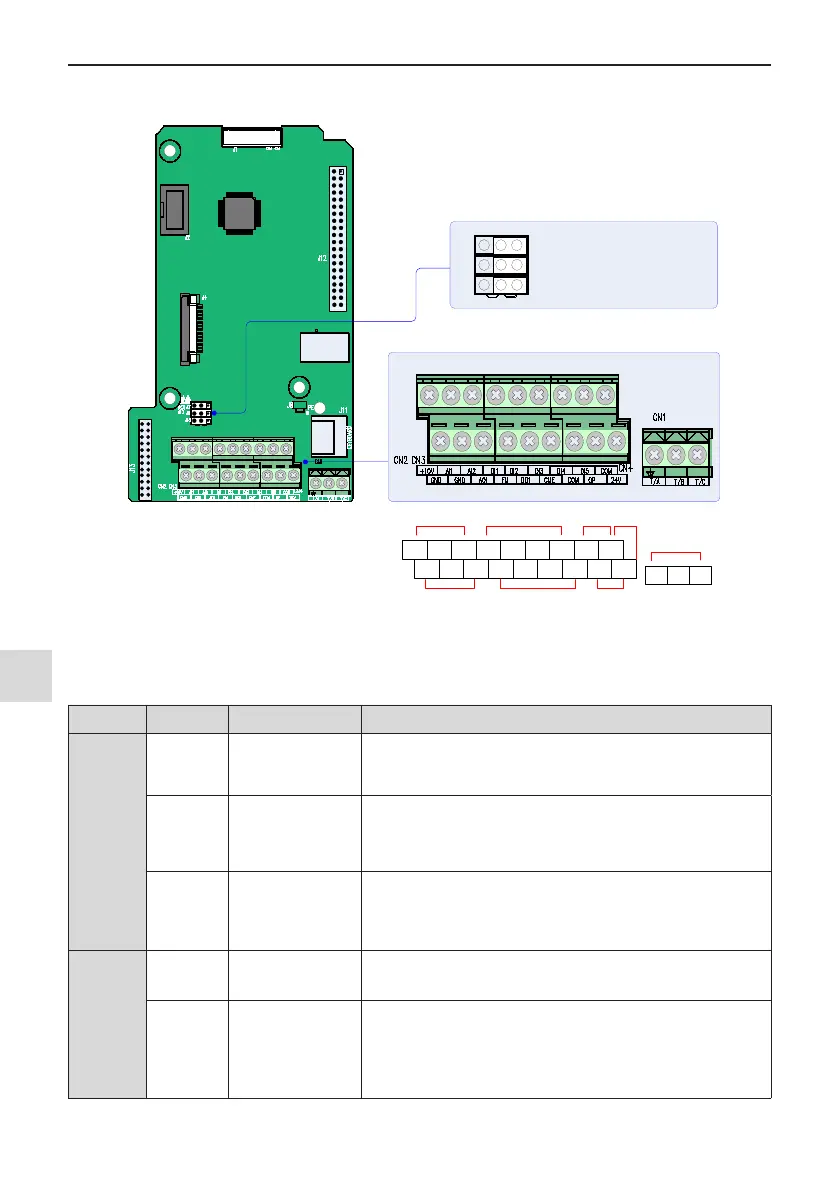
3.2.4 Control Circuit Terminal Arrangement
■
Control circuit terminal arrangement
+10V AI1
AI2 DI1 DI2 DI3 DI4 DI5
COM
GND GND AO1 FM DO1 CME COM OP +24V
T/A T/B T/C
Analog input and
power supply
Logic input Pulse input
Power
supply
Relay output
Analog output and
analog terminal
Pulse output and open-collector output
Logic public terminal
and power supply
AO1 output selection: voltage output by default
J7
J9
J10
I V
AI2 input impedance selection: 500 Ω by default, 250 Ω selectable
AI2 input selection: voltage input by default
Figure 3-39 Control circuit terminal arrangement
Table 3-6 Control circuit terminal function
Type Terminal Name Description
Power
supply
+10 V-GND +10 V power supply
Provides +10 V power supply to an external unit. Max. output current:
10 mA.
Generally used to supply an external potentiometer of 1 to 5 kΩ
+24 V-COM +24 V power supply
Provide +24 V power supply to an external unit. Generally used for
power supply for DI/DO terminals and external sensors.
Max. output current: 200 mA
<1>
OP
Input terminal for
external power
supply
Connected to +24 V by default.
When DI1 to DI5 need to be driven by external signals, OP must
be disconnected from + 24 V and connected to an external power
supply.
Analog
inputs
AI1-GND Analog input 1
Voltage range of inputs: 0 to 10 VDC
Input impedance: 22 kΩ
AI2-GND Analog input 2
Either a voltage or a current input, determined by jumper J9
Input voltage range: 0 to 10 VDC
Input current range: 0 to 20 mA
Input impedance: 22 kΩ (voltage input), 500 Ω or 250 Ω (current
input) decided byJ10
<2>

 Loading...