5 Basic Operations and Trial Run
-
70
-
5
5.9 View Running Status
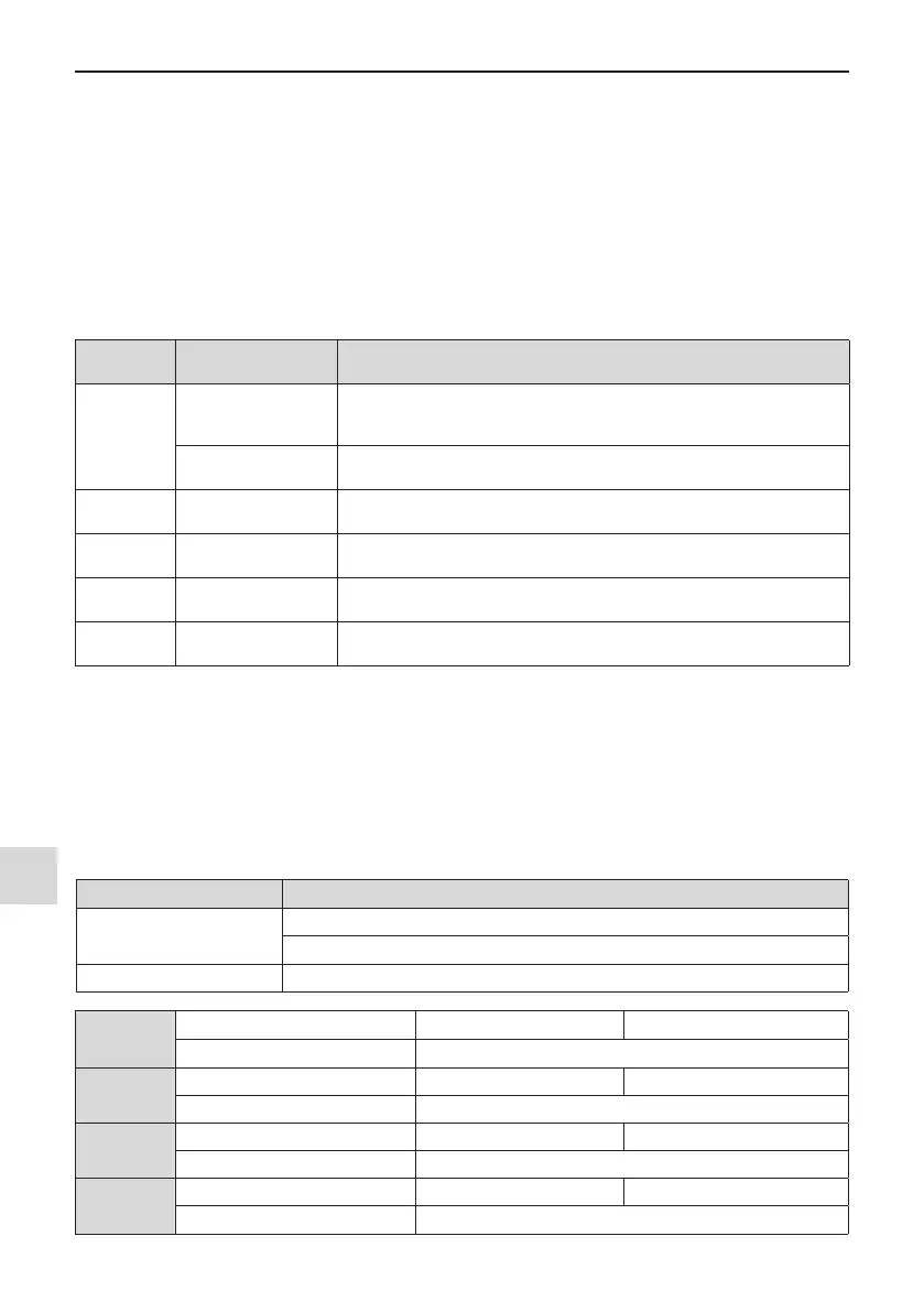
5.9.1 Digital Output (DO)
There are three digital output terminals on the control board. FM and DO1 are transistor outputs capable of
driving a 24 V DC low-voltage circuit. TA/TB/TC is a relay capable of driving a 250 V AC control circuit.
There are two additional digital outputs on the optional I/O extension board. DO2 is a transistor output and PA/
PB/PC is a relay output.
Function codes F5-01 to F5-05 dene how DO terminals indicate the running status and alarm information for
the AC drive. There are about 40 functions a with no-loadvailable to use for these function codes.
Terminal
Corresponding
Function Code
Output Feature Description
FM-COM
F5-06 when F5-00 = 0
Transistor
Able to output high-speed pulses 10 Hz to 100 KHz
Drive capacity: 24 VDC, 50 mA
F5-01 when F5-00 = 1
Transistor
Drive capacity: 24 VDC, 50 mA
TA-TB-TC F5-02
Relay
Drive capacity: 250 VAC, 3A
PA-PB-PC F5-03
Extension card, relay
Drive capacity: 250 VDC, 3A
DO1-CME F5-04
Transistor
Drive capacity: 24 VDC, 50 mA
DO2-CME F5-05
Extension card, transistor
Drive capacity: 24 VDC, 50 mA
When F5-00 = 0, FM terminal is high-speed pulse output. Frequency of pulses on this DO terminal indicates
the value of internal running parameters. Higher values of internal running parameters produce higher pulse
frequencies. Value 100% corresponds to a pulse frequency of 100 kHz. F5-06 indicates attributes of internal
running parameters.
5.9.2 Analog Output (AO)
The drive supports a maximum of two analog output terminals. AO1 is on the control board and AO2 is on the
optional extension card. F5-07 and F5-08 dene how AO terminals indicate the drive internal running parame-
ters in analog mode.
Terminal Input Signal Characteristics
AO1-GND
If J7 jumps to the "V" position, AO outputs voltage signal of 0 to 10 VDC.
If J7 jumps to the "I" position, AO outputs current signal of 0 to 20 mA.
AO2-GND It is on the optional extension card. It outputs voltage signal of 0 to 10 VDC.
F5-10
AO1 zero offset coefcient Default 0.0%
Setting Range -100.0% to +100.0%
F5-11
AO1 gain Default 1.00
Setting Range -10.00 to +10.00
F5-12
AO2 zero offset coefcient Default 0.00%
Setting Range -100.0% to +100.0%
F5-13
AO2 gain Default 1.00
Setting Range -10.00 to +10.00