5 Basic Operations and Trial Run
-
65
-
5
5.6 Motor Control
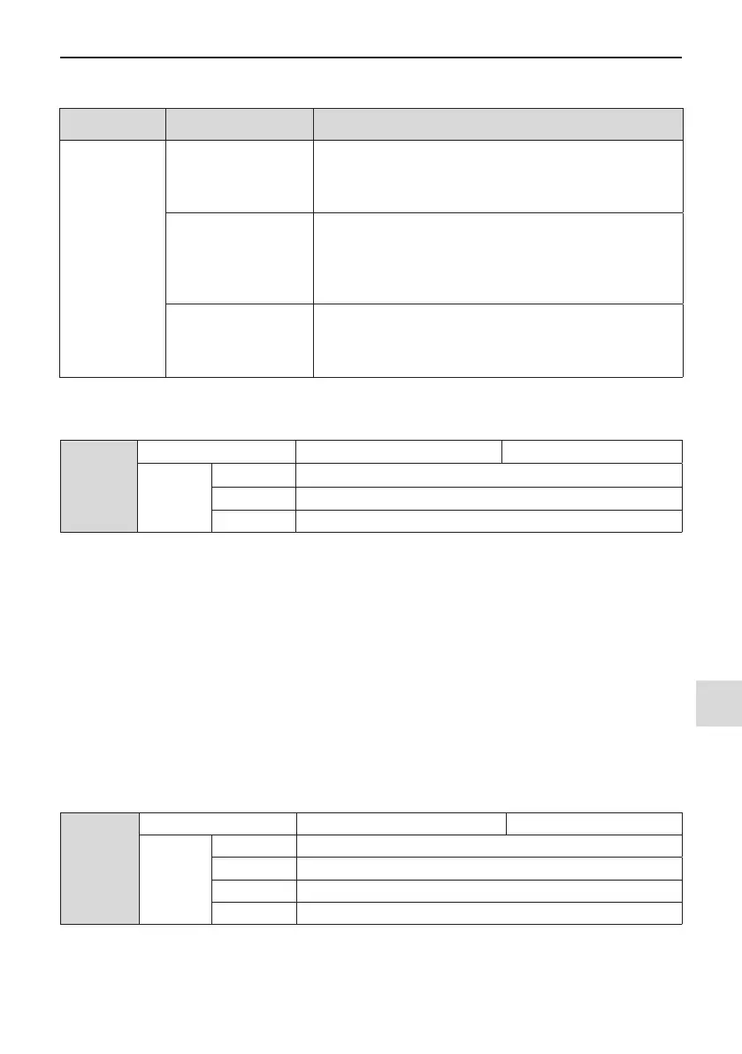
Function Code Description Scenario
F0-01: Motor
control mode
F0-01 = 0: SVC
It indicates the SVC control mode. It is applicable for common high-
performance control scenarios in which one AC drive can drive only
one motor, for example, machine tool, centrifuge, drawing machine,
and injection molding machine.
F0-01 = 1: FVC
It indicates the FVC control mode. The motor must have an encoder
and the drive must have a PG card in the same type of the encoder.
It is applicable to scenarios requiring high precision speed or torque
control. One AC drive can drive only one motor, for example, high-
speed paper making machine, crane and elevator.
F0-01 = 2: V/F
It is applicable to scenarios having no requirement on load or using
one drive to drive multiple motors, including fans and bumps. It is
applicable to scenarios in which one drive is used to drive multiple
motors.
5.7 Start/Stop running command
F0-02
Running command selection Default 0
Setting
Range
0 Operating panel (LED off)
1 Terminal (LED on)
2 Serial communication (LED ashing)
You can use F0-02 to select input channel of the drive running command. The drive running commands include
start, stop, forward, reverse, and jog.
F0-02 = 0: Operating panel (The LOCAL/REMOT indicator is off.)
The commands are given by pressing the RUN and STOP/RES on the operating panel.
F0-02 = 1: Terminal (The LOCAL/REMOT indicator is on.)
Commands are given by using multi-functional input terminals with functions such as FWD, REV, JOGF and
JOGR.
F0-02 = 2: Serial communication (The LOCAL/REMOT indicator is ashing.)
5.7.1 Start/Stop Operating Panel
The commands are given by pressing the RUN and STOP/RES on the operating panel, and the LOCAL/RE-
MOT indicator is off. For information about the keys, refer to Chapter 4 Panel Operations.
5.7.2 Start/Stop DI
F4-11
Terminal I/O control mode Default 0
Setting
Range
0 Two-wire control mode 1
1 Two-wire control mode 2
2 Three-wire control mode 1
3 Three-wire control mode 2
F4-11 denes the four terminal I/O control modes, in which the drive running is controlled by DI terminals.

 Loading...