4 Panel Operation
-
57
-
4
Function
Code
Parameter
Name
Default
Setting
Range
Description
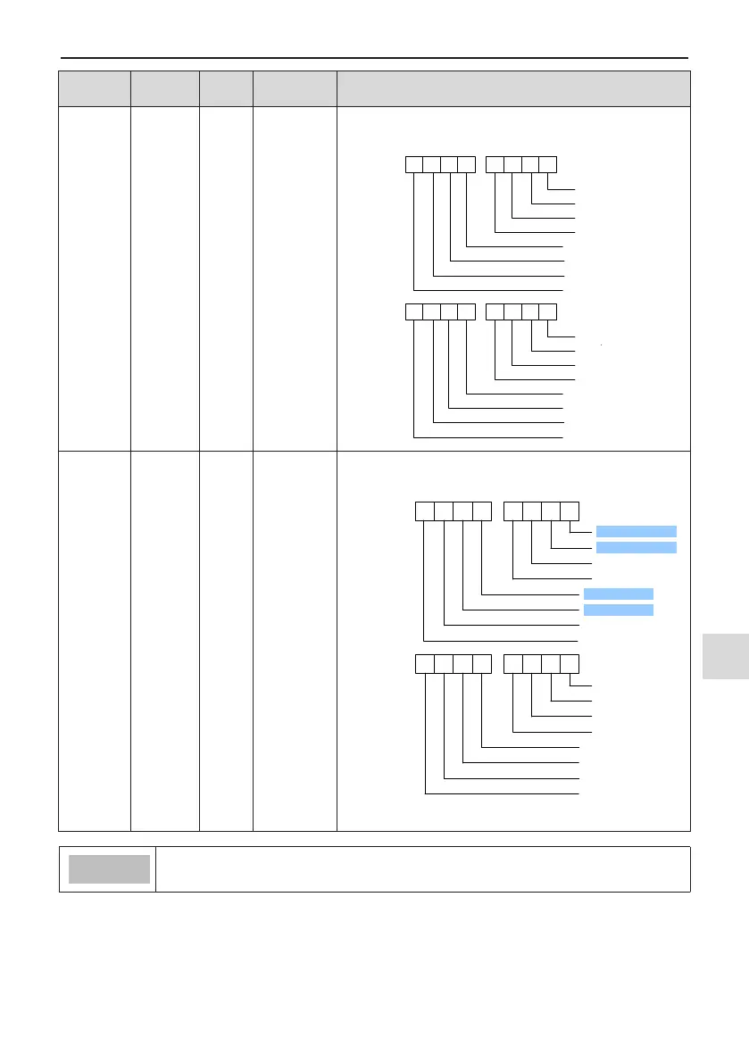
F7-04
LED
display
running
parameters
2
0
0000 to FFFF
If a parameter needs to be displayed during running, set cor-
responding bit to 1, and set F7-04 to hexadecimal equivalent.
7 6 5 4 3 2 1 0
PID feedback
PLC stage
Input pulse frequency (kHz)
Running frequency 2 (Hz)
Remaining running time
AI1 voltage before correction (V)
Lowest
eight digits
15 14 13 12 11 10 9 8
Highest
eight digits
AI2 voltage before correction (V)
Motor speed
Current power-on time (H)
AI3 voltage before correction (V)
Current running time (Min)
Input pulse frequency (Hz)
Communication reference
Reserved
Main frequency display (Hz)
Auxiliary frequency display (Hz)
F7-05
Display
stop
parameter
0
0000 to FFFF
If a parameter needs to be displayed during stop, set
corresponding bit to 1, and set F7-05 to hexadecimal equivalent.
7
6 5
4 3
2
1 0
Frequency reference (Hz)
Bus voltage (V)
DI state
DO state
AI1 voltage (V)
Count value
15 14
13 12
11
10 9
8
Length value
PLC stage
Load speed
PID reference
Input pulse frequency (Hz)
Reserved
Reserved
Reserved
Lowest eight
digits
Highest eight
digits
AI2 voltage (V)
AI3 voltage (V)
Note: Values with shading are default values.
● Once the AC drive is re-powered on after power down, the display includes the selected
parameters before power down by default.

 Loading...