Remote Control
Copyright © ITECH Electronic Co., Ltd. 11
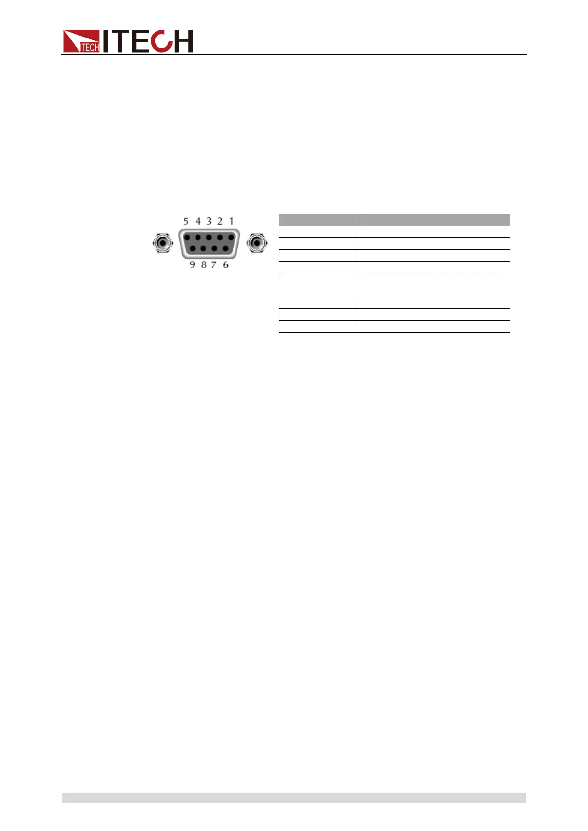
RS-232 connections
The RS-232 serial port can be connected to the serial port of a controller (i.e.,
personal computer) using a straight through RS-232 cable ended with DB-9
connectors.
Note: Do not usea null modem cable.
If your computer uses a DB-25 connector for the RS-232 interface, you will
need a cable or adapter with a DB-25 connector on one end and a DB-9
connector on the other, wired straight through.
The following figure and table show the pins for the connector.
RS-232 troubleshooting
If you are having trouble communicating over the RS-232 interface, check the
following:
The computer and the electronic load must be configured for the same
baud rate, parity, number of data bits, and flow control options. Note that
the electronic load is configured for 1 start bit and 1 stop bit (these values
are fixed).
The correct interface cables or adapters must be used, as described under
RS-232 Connector. Note that even if the cable has the proper connectors
for your system, the internal wiring may be incorrect.
The interface cable must be connected to the correct serial port on your
computer (COM1, COM2,etc.).
USB-TMC Capabilities of the Electronic Load
All electronic load functions are programmable over the USB.
The USB488 interface capabilities of the electronic load are described as
follows:
The interface is a 488.2 USB488 interface.
The interface accepts REN_CONTROL, GO_TO_LOCAL, and
LOCAL_LOCKOUT requests.
The interface accepts the MsgID = TRIGGER USBTMC command
message and forwards TRIGGER requests to the Function Layer.
The USB488 device capabilities of the electronic load are described follow:
The device understands all mandatory SCPI commands.
The device is SR1 capable
The device is RL1 capable
The device is DT1 capable
1.10 Queue
The IT8800 Series uses two queues, which are first-in, first-out (FIFO)

 Loading...


