Home
JUKI
Sewing Machine
AMS-221EN Series
JUKI AMS-221EN Series User Manual
5
of 1
of 1 rating
253 pages
Give review
Manual
Specs
To Next Page
To Next Page
To Previous Page
To Previous Page
Loading...
– 153 –
6. T
est mode
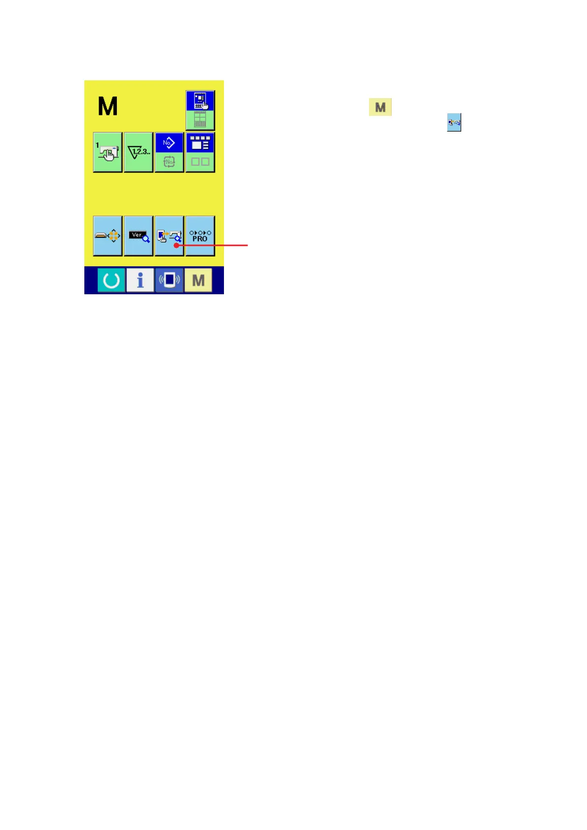
1)
Display of the check program screen
When the
key is continuously pressed for 3
seconds, the check program
(A) is displayed on
the screen. When this button is depressed, the check
program screen is displayed.
A
156
158
Table of Contents
Default Chapter
3
Table of Contents
3
1 Specifications
5
2 Configuration
6
Names of Main Unit
6
Operation Panel
7
3 Standard Adjustment
8
Adjustment of the Throat Plate Auxiliary Cover Height
8
Adjustment of the Feed Bar Auxiliary Cover Rail X
10
Adjustment of the X Movement Top Cover
10
Main Shaft Connection/Disconnection
12
Removal of Main Shaft Motor and Coupling
14
Crank Rod Connection/Disconnection
16
Crank Balancer Positioning
18
Adjustment of Intermediate Presser Cam
20
Adjustment of Intermediate Presser Bar
20
Intermediate Presser Variable Connection/Disconnection
22
Intermediate Presser Variable Adjustments
24
Intermediate Presser Drive Arm
26
Lower Shaft Backlash Adjustment and Connection/Disconnection
28
Oscillator Gear Positioning
28
Adjustment of Hook Oil Amount
30
Shuttle Connection / Disconnection and Oil Wick Piping
30
Adjusting the Height of the Needle Bar
32
Hook Adjustment
34
Thread Trimmer Presser Lifter Cam Connection/Disconnection
36
Thread Trimmer and Presser Origin Sensor Adjustment
36
Adjustment of the Moving Knife and Counter Knife Position
38
Floating Amount of the Thread Tension Disk
38
Second Thread Tension Connection / Disconnection
40
AT Unit Connection / Disconnection
42
Wiper Adjustment
44
Backlash Adjustment for the X Motor
46
Backlash Adjustment for the y Motor
46
Adjustment of the Tension of the X Timing Belt
48
Adjustment of the Tension of the y Timing Belt
50
How to Remove Rattles from the y Drive Shaft
52
Phase Adjustment for the y Timing Belt
52
Adjustment of the X-Y Mechanism
54
Pressure Adjustment for the Side Plate Bearing
56
Initial Length of the Presser Cylinder
58
Initial Length of the 2-Step Stroke Cylinder
58
Adjustment of the Speed Controller
60
Adjustment of the Pressure Reducer
62
Making the Origin Setting Gauge
64
Adjusting the X Origin Sensor
64
Adjusting the y Origin Sensor
66
Adjustment of the Bobbin Winder Driving Wheel Position
68
Adjusting the Bobbin Winder Amount
68
Adjustment of the Shuttle Upper Spring and Lower Thread Holder Position
70
Shuttle Felt
70
Shape of the Shuttle Race Ring
72
Adjustment of Thread Take-Up Spring
72
Needle Thread Clamp Device Connection/Disconnection
74
Adjusting the Needle Thread Clamp Notch
76
Adjusting the Needle Thread Clamp Sensor
78
Adjustment of Tilt Machanism of the Machine Head
80
4 Memory Switch
86
Start and Change
86
Function List
87
5 Supplemental Remarks of each Function Number and Explanation of each Function
104
Feeding Frame Operational Sequence Setup
104
Fixed Refuge Position Setup
108
Bank Function Setup
109
Port I/O Setup
112
Simplified Program Setup
125
Version Display
138
Keylock Setup
139
Customize Function Setting of Key Lock
141
Communication Screens of the Maintenance Personnel Level (Program Rewrite)
148
Information Screen at the Maintenance Personnel Level
152
Test Sewing Function
154
6 Test Mode
157
7 Printed Wiring Board and Dip Switch
173
Various Printed Wiring Boards
173
Dipswitch Setup
181
8 Table of Exchanging Gauge Parts According to Sewing Specifications and Needle Size Used
182
9 Option List
183
Method of Pedal Switch Cable Set Connections
190
10 Maintenance
192
Replacing the Fuse
192
Changing the Voltage Specification
193
Greasing• Lock-Tight Parts
194
Parts to Which Grease • Locktight Is Applied
195
Replenishing the Designated Places with Grease
204
11 Error Code List
209
12 Message List
217
13 Troubles and Corrective Measures
221
Mechanical Parts
221
Sewing Conditions
225
Electrical Components
234
14 Circuit Diagrams
243
Block Diagram
243
Power Supply Circuit Diagram a
244
Power Supply Circuit Diagram B
245
Power Supply Circuit Diagram C
246
Servo Motor Circuit Diagram
247
Sensor-Pedal Circuit Diagram
248
MAIN•PANEL Board Circuit Diagram
249
Motor•Solenoid Circuit Diagram
250
Air System Circuit Diagram
251
15 Drawing of the Table
252
5
Based on 1 rating
Ask a question
Give review
Questions and Answers:
Need help?
Do you have a question about the JUKI AMS-221EN Series and is the answer not in the manual?
Ask a question
JUKI AMS-221EN Series Specifications
General
Brand
JUKI
Model
AMS-221EN Series
Category
Sewing Machine
Language
English
Related product manuals
JUKI AMS-221EN/IP-420
121 pages
JUKI AMS-221ENTS
133 pages
JUKI AMS-221D
272 pages
JUKI AMS-229B
68 pages
JUKI AMS-224C
272 pages
JUKI AMS-224EN-4530
133 pages
JUKI AMS-224EN4530R
133 pages
JUKI AMS-224EN/IP-420
120 pages
JUKI AMS-205C
272 pages
JUKI AMS-206C
272 pages
JUKI AMS-210EN/IP-420
133 pages
JUKI APW-895/IP-420
124 pages