 Loading...
Do you have a question about the JUKI AMS-221EN Series and is the answer not in the manual?
| Brand | JUKI |
|---|---|
| Model | AMS-221EN Series |
| Category | Sewing Machine |
| Language | English |
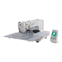
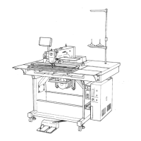
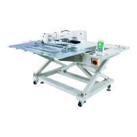
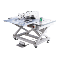
Labels the various parts of the sewing machine's main unit.
Describes the functions and layout of the IP-420 operation panel.
Instructions for adjusting the height of the throat plate auxiliary cover.
Steps to adjust the feed base auxiliary cover rail X.
Procedures for adjusting the X movement top cover.
Detailed steps for connecting and disconnecting the main shaft.
Instructions for removing the main shaft motor and its coupling.
Steps for connecting and disconnecting the crank rod.
How to correctly position the crank balancer for optimal operation.
Steps for adjusting the intermediate presser cam.
Procedure for adjusting the intermediate presser bar.
Detailed steps for connecting and disconnecting the intermediate presser variable.
Instructions for performing variable adjustments on the intermediate presser.
Adjustment procedures for the intermediate presser drive arm.
How to adjust lower shaft backlash and connect/disconnect it.
Steps to ensure the correct positioning of the oscillator gear.
Procedure for adjusting the amount of oil supplied to the hook.
Steps for connecting/disconnecting the shuttle and its oil wick piping.
How to adjust the height of the needle bar for correct operation.
Detailed instructions for adjusting the hook mechanism for proper sewing.
Steps for connecting and disconnecting the thread trimmer presser lifter cam.
Procedures for adjusting the origin sensors for the thread trimmer and presser.
How to adjust the positions of the moving and counter knives.
Adjusting the floating amount of the thread tension disk.
Steps for connecting and disconnecting the second thread tension unit.
Instructions for connecting and disconnecting the AT unit.
Procedure for adjusting the wiper mechanism to ensure proper operation.
How to adjust backlash for the X motor to ensure smooth movement.
How to adjust backlash for the Y motor for smooth operation.
Procedures for adjusting the tension of the X timing belt.
Steps to adjust the tension of the Y timing belt.
Methods to eliminate rattles from the Y drive shaft.
How to perform phase adjustments for the Y timing belt.
Detailed instructions for adjusting the X-Y mechanism.
How to adjust the pressure for the slide plate bearing.
Setting the initial length for the presser cylinder.
Setting the initial length for the 2-step stroke cylinder.
How to adjust the speed controllers for cylinders.
Procedure for adjusting the pressure reducer for the presser cylinders.
How to create an origin setting gauge for sensor adjustments.
Steps to adjust the X origin sensor for proper positioning.
Instructions for adjusting the Y origin sensor for correct positioning.
How to adjust the position of the bobbin winder driving wheel.
Procedure for adjusting the amount of thread wound on the bobbin.
Adjusting the shuttle upper spring and lower thread holder positions.
Information regarding the shuttle felt and its proper installation.
Specifications for the shuttle race ring shape and wear check.
How to adjust the thread take-up spring's stroke and tension.
Steps for connecting and disconnecting the needle thread clamp device.
How to adjust the notch position of the needle thread clamp.
Procedure for adjusting the needle thread clamp sensor.
Steps to fix and adjust the position of the lifter brackets.
How to adjust the position of the falling stopper for safety.
Adjusting the spring tension for the falling stopper's ON/OFF function.
Procedure for replacing the gas spring in the machine head mechanism.
Steps to start and modify settings in the memory switch.
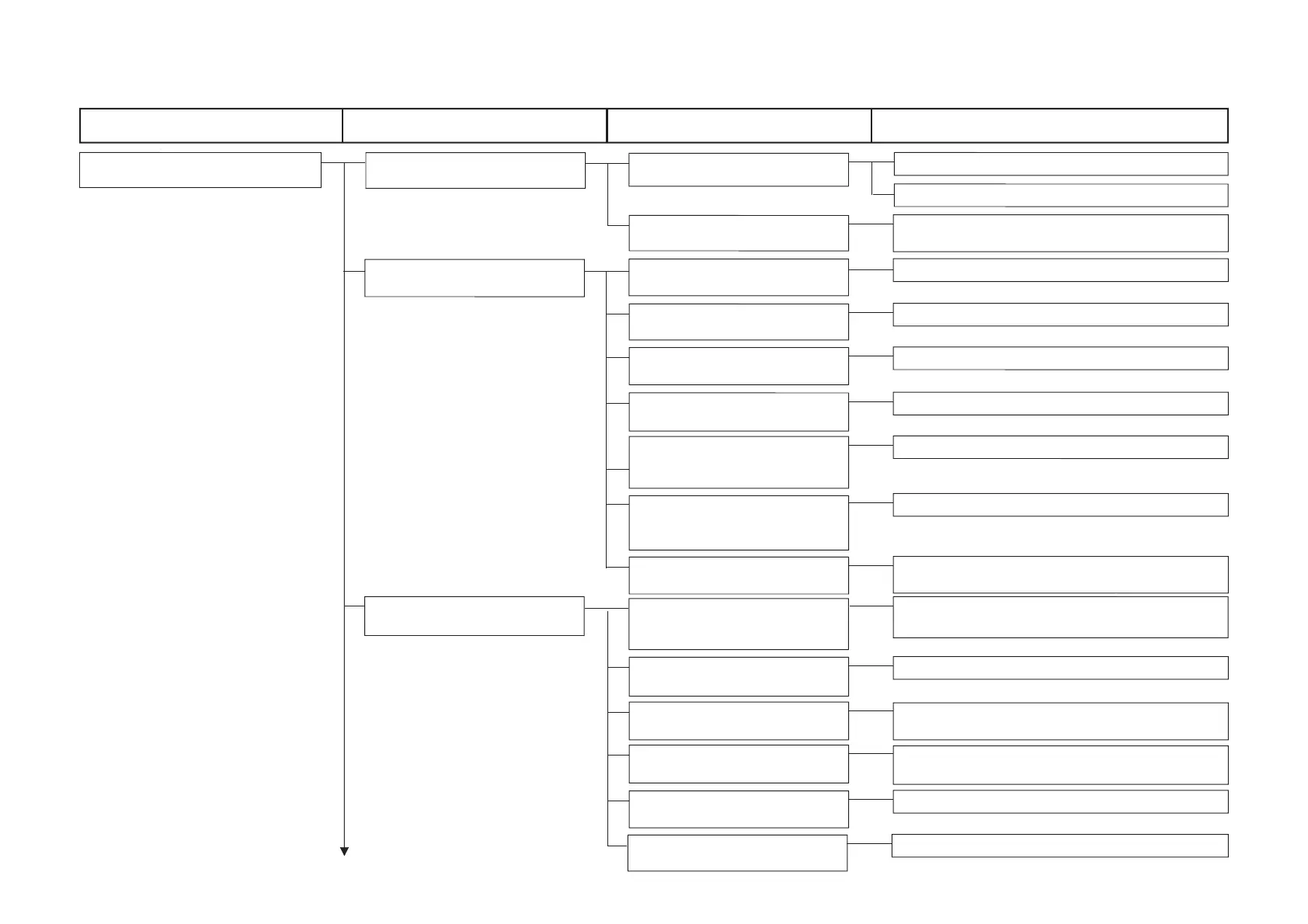
A list of functions configurable via memory switches, with their ranges and initial values.
How to set up the operational sequence for the feeding frame.
Setting up the driving methods for the feeding frame and pedal operation.
Configuring the feeding frame sequence using temporary stop commands.
Setting the timing for feeding frame lifting at the end of sewing.
Setting up the feeding frame lifting timing during temporary stops.
Configuring settings to prohibit feeding frame lifting.
Setting up the operational methods for the presser pedal.
How to select whether the fixed refuge position is used or not.
Setting up the X and Y coordinates for the fixed refuge position.
Setting up the number of banks and barcode function.
Configuring the input terminal numbers for the bank function.
Setting up the functions for various input terminals.
Configuring functions for various output terminals.
Overview of the capabilities and limits of the simplified program.
Details the five items configurable for each step in a simplified program.
How simplified programs are executed sequentially and controlled.
Describes the steps for operating and managing simplified programs.
How to display the screen for selecting simplified programs.
Enabling or disabling the simplified program function.
Steps for editing and modifying simplified programs.
Detailed steps for editing commands, I/O setup, and parameters in simplified programs.
Entering parameter values for simplified program steps.
How to insert new steps into a simplified program.
Viewing the status of simplified programs while operating the sewing machine.
An example program for material stacking during sewing.
A second example program for material stacking operations.
Illustrations and descriptions of the different printed wiring boards.
Instructions for setting up the dipswitches on various boards.
List of parts required for the pedal switch cable set.
Details on the correct mounting position for switches.
Changes to memory switches for pedal operation customization.
Items related to the control of pedal operations.
Diagram illustrating switch mounting positions.
Step-by-step guide on how to replace fuses in the machine.
Instructions for changing the machine's voltage specifications.
Information on recommended greases and parts requiring lock-tight application.
Step-by-step guide on where and how to apply grease.
Detailed steps for applying grease to specific locations.
Steps for receiving data from PM-1 and editing vector parameters.
How to modify data, execute test sewing, and register it.
Viewing recorded error codes and their details for troubleshooting.
Accessing data on cumulative operating time, thread trimming, and stitch counts.
How to access the check program screen within test mode.
Calibrating the touch panel for accurate input.
Verifying the functionality and dot integrity of the LCD display.
How to check the status of various input signals and sensors.
Checking the main motor's RPM and operation.
How to check the status of various output signals.
Verifying the operation of XY motors and their origin sensors.
Checking presser and thread trimmer motors and their origin sensors.
Verifying the needle thread clamp motor and its origin sensor.
How to set up and perform continuous operation.
Checking the intermediate presser motor and its origin sensor.
Illustrations and descriptions of the different printed wiring boards.
Instructions for setting up the dipswitches on various boards.
List of parts required for the pedal switch cable set.
Details on the correct mounting position for switches.
Changes to memory switches for pedal operation customization.
Items related to the control of pedal operations.
Diagram illustrating switch mounting positions.
Troubleshooting guide for mechanical problems encountered with the sewing machine.
Troubleshooting guide for problems related to sewing conditions and thread issues.
Troubleshooting guide for electrical issues and component identification.
A high-level overview of the machine's system architecture.
Diagram showing the first configuration of the power supply circuit.
Diagram showing the second configuration of the power supply circuit.
Diagram showing the third configuration of the power supply circuit.
Illustration of the servo motor's electrical connections.
Diagram showing the wiring for sensors and pedals.
Electrical diagram for the MAIN and PANEL boards.
Electrical diagram for motor and solenoid connections.
Diagram illustrating the pneumatic system and solenoid valves.