FX-3R Maintenance Guide
8-20
5) Adjust the potentiometer.
Adjust the potentiometer after the sensor mounting position, mounting position in the
Y-direction (sensor is secured to the center of the oval hole in the sensor BR), and optical axis
have been adjusted.
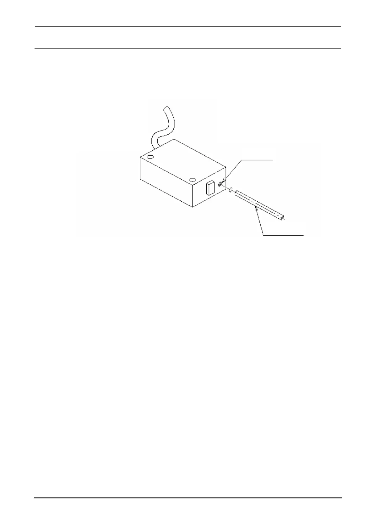
Figure 8-3-6-2 Adjustment of Potentiometer
Potentiometer
Precision screwdriver
Right
Left
c Turn the potentiometer on the light emitting side toward the Min. side (left side) to put the
sensor in the interruption status.
d Gradually turn the potentiometer toward the Max. side (right side) and stop turning at a
position where both the red and green lamps on the light receiving side are lit.
e Check that the ETF, which is placed on the guide rail and inserted, is detected.
Rev. 1.00

 Loading...


