Front Panel Operation
2-82
Typically, you would want the Model 6517A to output a trig-
ger after the settling time of each measurement. (Settling
time includes the internally set measurement settling time
and the user programmed DELAY period.) An output com-
pletion pulse occurs after each measurement as long as the
measure source is set to external, timer, manual, or immedi-
ate. See paragraphs 2.15.2 and 2.15.3 for details.
The Model 6517A can also output a completion pulse while
in the scan and/or arm layers of operation. Figure 2-57 shows
where these triggers occur in the trigger model. If the scan
layer Source Bypass is enabled (Control = Source) and the
Scan Source is programmed for External, an output trigger
occurs on each return path through the scan layer. If the arm
layer Source Bypass is enabled (Control = Source) and the
Arm Source is programmed for External, an output trigger
occurs on each return path through the arm layer. See para-
graph 2.15.3 for programming the scan and arm layers.
Meter
Complete
TTL High
(3.4V Typical)
TTL Low
(0.25V Typical)
10µs
Minimum
Figure 2-60
Meter complete and asynchronous trigger link output
pulse specifications
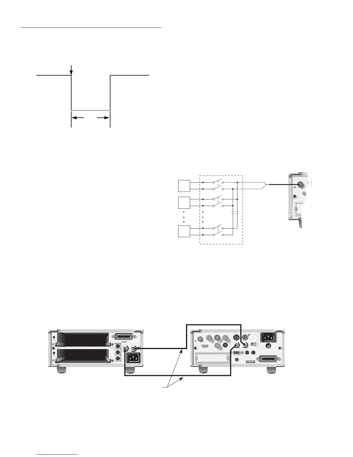
External triggering example #1
In a typical test system, you may want to close a channel and
then measure the DUT connected to that channel with a mul-
timeter. Such a test system is shown in Figure 2-61, which
uses a Model 6517A Electrometer to measure ten DUTs
switched by a Model 7158 multiplexer card in a Model 7001
or 7002 Switch System.
The external trigger connections for this test are shown in
Figure 2-62. Channel Ready (output) of the Model 7001 or
7002 is connected to External Trigger Input of the Model
6517A. Meter Complete Output of the Model 6517A is con-
nected to External Trigger (input) of the Model 7001 or
7002. For this example, the Models 6517A and 7001/7002
are configured as follows:
Figure 2-61
DUT test system
1
2
10
OUTPUT
Card 1
7158 MUX Card
DUT
#1
DUT
#2
DUT
#10
6517A
INPUT
250V PEAK
!
Channel
Ready
External
Trigger
7001 or 7002 Switch System
7051-2
BNC to BNC
Cables (2)
MTR
COMP
OUT
6517A
EXT
TRIG
IN
WARNING:
NO INTERNAL OPERATOR SERVICABLE PARTS,SERVICE BY QUALIFIED PERSONNEL ONLY.
WARNING:
NO INTERNAL OPERATOR SERVICABLE PARTS,SERVICE BY QUALIFIED PERSONNEL ONLY.
CAUTION:
FOR CONTINUED PROTECTION AGAINST FIRE HAZARD,REPLACE FUSE WITH SAME TYPE AND RATING.
CAUTION:
FOR CONTINUED PROTECTION AGAINST FIRE HAZARD,REPLACE FUSE WITH SAME TYPE AND RATING.
IEEE
-
488
CHANNEL
READY
EXTERNAL
TRIGGER
O
U
T
I
N
C
A
R
D
90
-
250
V
50
-
400
Hz
40VA
MAX
LINE
RATING
2
TRIGGER LINK
DIGITAL I/O
C
A
R
D
1
MADE IN USA
WARNING:
NO INTERNAL OPERATOR SERVICABLE PARTS,SERVICE BY QUALIFIED PERSONNEL ONLY.
WARNING:
NO INTERNAL OPERATOR SERVICABLE PARTS,SERVICE BY QUALIFIED PERSONNEL ONLY.
CAUTION:
FOR CONTINUED PROTECTION AGAINST FIRE HAZARD,REPLACE FUSE WITH SAME TYPE AND RATING.
CAUTION:
FOR CONTINUED PROTECTION AGAINST FIRE HAZARD,REPLACE FUSE WITH SAME TYPE AND RATING.
INPUT
250V PEAK
!
LINE RATING
50-60HZ
50VA MAX
AC ONLY
LINE FUSE
SLOWBLOW
1/2A 90-125V
1/4A 180-250V
IEEE-488
(CHANGE IEEE ADDRESS
WITH FRONT PANEL MENU)
DIGITAL
I/O
TRIG LINK
115V
Figure 2-62
External trigger connections

 Loading...


