IEEE-488 Reference
3-14
3.8.1 Condition registers
As shown in the illustrations, all status register sets, except
the standard event status register set, have a condition regis-
ter. A condition register is a real-time read-only register that
constantly updates to reflect the current operating conditions
of the instrument. For example, while a calculation is being
performed, bit B9 (Calc) of the Operation Condition Regis-
ter is set. When the calculation is completed, bit B9 clears.
The :CONDition? query commands in the STATus Sub-
system are used to read the condition registers. See para-
graph 3.20 for details.
3.8.2 Transition filters
As shown in the illustrations, all status register sets, except
the standard event status register set, have a transition filter.
A transition filter is made up of two registers that are pro-
grammed by the user. It is used to specify which transition (0
to 1, or 1 to 0) in the corresponding condition register will set
the corresponding bit in the event register.
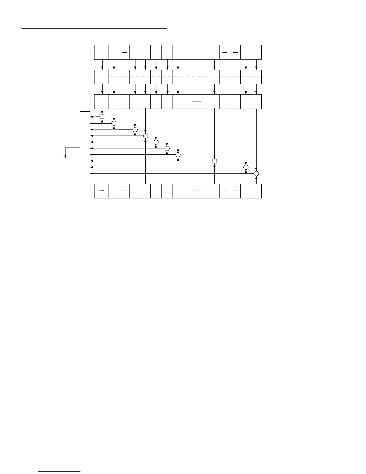
Figure 3-12
Questionable event status
(B14) (B8)(B15)
OR
Questionable
Condition
Register
Questionable
Event Enable
Register
Warn = Command Warning
Seq = Sequence Test Summary
Coul = Coulombs Summary
Ohm = Ohms Summary
Hum = Humidity Summary
&
&
(B14) (B8)(B15)
Cal
(B14) (B8)(B15)
Warn Cal
PTR
NTR
Questionable
Transition
Filter
Questionable
Event
Register
(B14) (B8)(B15)
To Questionable
Summary Bit
(QSB) of Status
Byte Register
(See Figure 3-13).
(B7 - B5)
(B7 - B5)
(B7 - B5)
(B7 - B5)
Warn Cal
Warn Cal
&
(B4)
Temp
(B4)
Temp
(B4)
Temp
(B4)
Temp
Warn
(B13)
(B13)
(B13)
(B13)
(B12)
(B12)
(B12)
Seq
(B12)
Seq
Seq
Seq
&
(B11)
(B11)
(B11)
Coul
(B11)
Coul
Coul
Coul
&
(B10)
(B10)
(B10)
Ohms
(B10)
Ohms
Ohms
Ohms
&
(B9)
(B9)
(B9)
Hum
(B9)
Hum
Hum
Hum
&
(B3)
(B3)
(B3)
(B3)
(B2)
(B2)
(B2)
(B2)
(B1)
&
(B1)
Amp
(B1)
Amp
(B1)
Amp
Amp
(B0)
&
(B0)
Volt
(B0)
Volt
(B0)
Volt
Volt
& = Logical AND
OR = Logical OR
PTR = Positive Transition Register
NTR = Negative Transition Register
Cal = Calibration Summary
Temp = Temperature Summary
Amp = Amps Summary
Volt = Volts Summary
Always
Zero
Always
Zero
Always
Zero
&
0
0
0
A filter can be programmed for positive transitions (PTR),
negative transitions (NTR) or both. When an event is pro-
grammed for a positive transition, the corresponding bit in
the event register sets when the corresponding bit in the con-
dition register changes for 0 to 1. Conversely, when pro-
grammed for a negative transition, the bit in the event register
sets when the corresponding bit in the condition register
changes from 1 to 0.
The :PTR and :NTR commands in the Status Subsystem are
used to set or clear the individual bits of the transition filter
registers, while the :PTR? and :NTR? query commands are
used to read the registers (see paragraph 3.20 for details).
Reading a transition filter register does not affect its bit pat-
tern.
The following operations set (1) all bits of all PTR registers
and clear (0) all bits of all NTR registers:
• Cycling power
• Sending :STATus:PRESet

 Loading...


