Front Panel Operation
2-119
STROBE-CONTROL
This menu item enables or disables the use of digital output
#4 as a binning strobe signal.
If enabled, the strobe signal is set TRUE for greater than 10
microseconds after all limit tests have been performed on a
new reading. The FALSE to TRUE transition can be used to
trigger an external device handler to check digital outputs
#1-3 for sorting parts into bins.
When binning is enabled from the front panel or with the bus
command :CALCulate3:BSTRobe:STATe ON, the binning
strobe signal is set to FALSE. When binning is disabled, the
strobe signal is left unchanged.
DISABLED: Use this selection to disable strobe control.
ENABLED: Use this selection to enable strobe control.
PASS-PATTERN
This item allows you to program the on/off states of the dig-
ital output lines for when all limit tests pass. Note that when
the binning strobe is enabled, digital output line #4 cannot be
used.
Selecting PASS-PATTERN displays the digital output pat-
tern that occurs when all limit tests pass. To change the pat-
tern, use the cursor keys and the range keys. The range keys
toggle the parameter values between OFF and ON.
Limits example
This example sorts a quantity of 100kΩ resistors into five
bins, according to the following tolerances:
•Values less than 90kΩ (outside -10% tolerance).
•Values greater than 110kΩ (outside +10% tolerance).
•Values between 90kΩ and 99kΩ (meets -10% toler-
ance).
•Values between 101kΩ and 110kΩ (meets +10% toler-
ance).
•Values between 99kΩ and 101kΩ (meets ±1% toler-
ance).
The desired test is shown in Figure 2-78. Use the following
procedure to program the limits:
1. From the LIMITS menu, set the limit values and actions
according to the following table:
2. Enable the binning strobe signal from the STROBE-
CONTROL item of the LIMITS menu.
3. Set a pass pattern of all lines off from the PASS PAT-
TERN item of the LIMITS menu.
4. Enable the control of the digital output lines by limit set
#1 and limit set #2 from the LIMIT SET #1 and LIMIT
SET #2 menus. This sets the digital output lines to the
“pass pattern” (all OFF in this example). Since binning
is enabled, digital output #4 is also OFF.
Note that the actual state (high or low) of the digital output
lines depends on the polarity (ACTIVE-HIGH or ACTIVE-
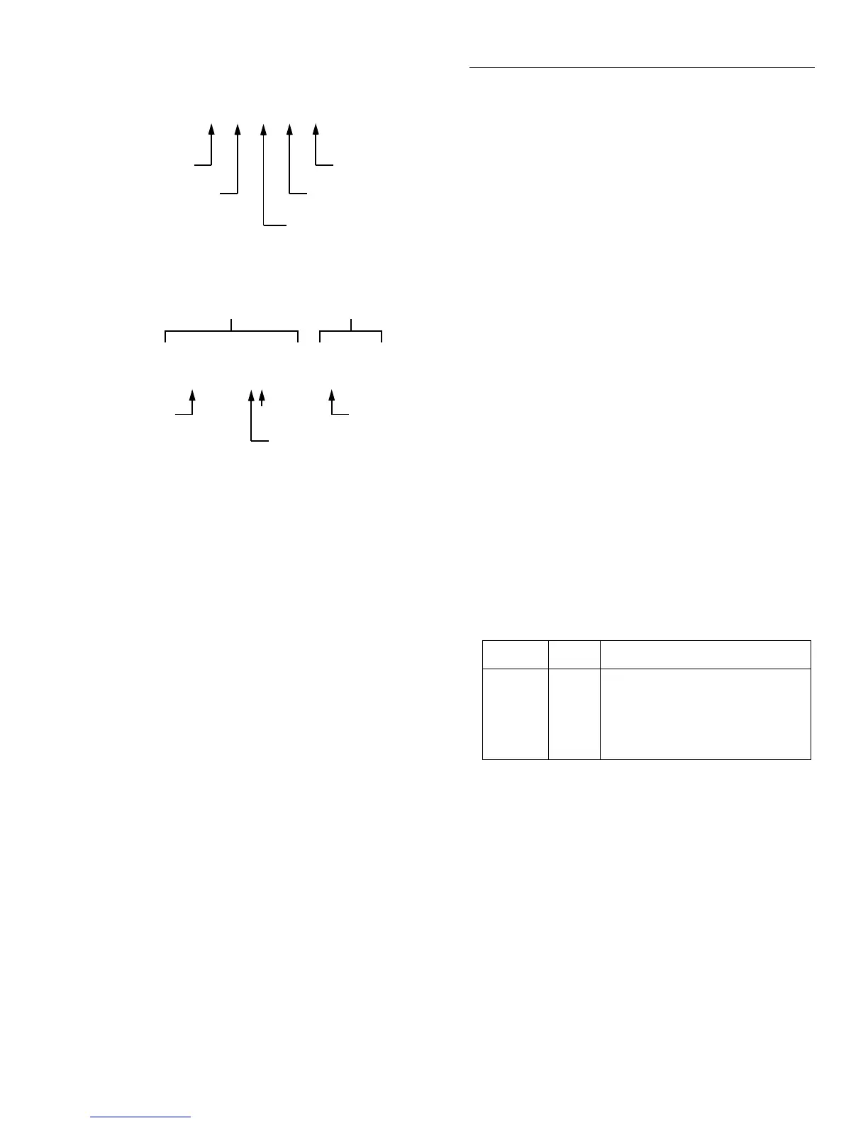
Figure 2-77
Limits bar graph example
LLIM1 | | | | | HLIM1
Low Limit #1
Average of midpoint
and Low Limit #1
High Limit #1
Average of midpoint
and High Limit #1
Midpoint of Low Limit #1
and High Limit #1
A. Defined points of display
Reading Pass/Fail indication
-0.2836 V PASS
NOTES : 1. Press INFO to view the programmed Low Limit #1 and
High Limit #1 values.
2. Multiple display of limit values do not use unit prefixes
(i.e., volts not millivolts).
B. Example Display with Limits = ±1V
-1V
LLIM1 | | ===| | | HLIM1
1V
0V
30% of difference between
midpoint and Low Level #1
Limit Value Action
LOLIM1
HILIM1
LOLIM2
HILIM2
90kΩ
110kΩ
99kΩ
101kΩ
DIGOUT1=ON, others OFF
DIGOUT2=ON, others OFF
DIGOUT1=ON, DIGOUT2=ON,
others OFF
DIGOUT3=ON, others OFF

 Loading...


