Front Panel Operation
2-10
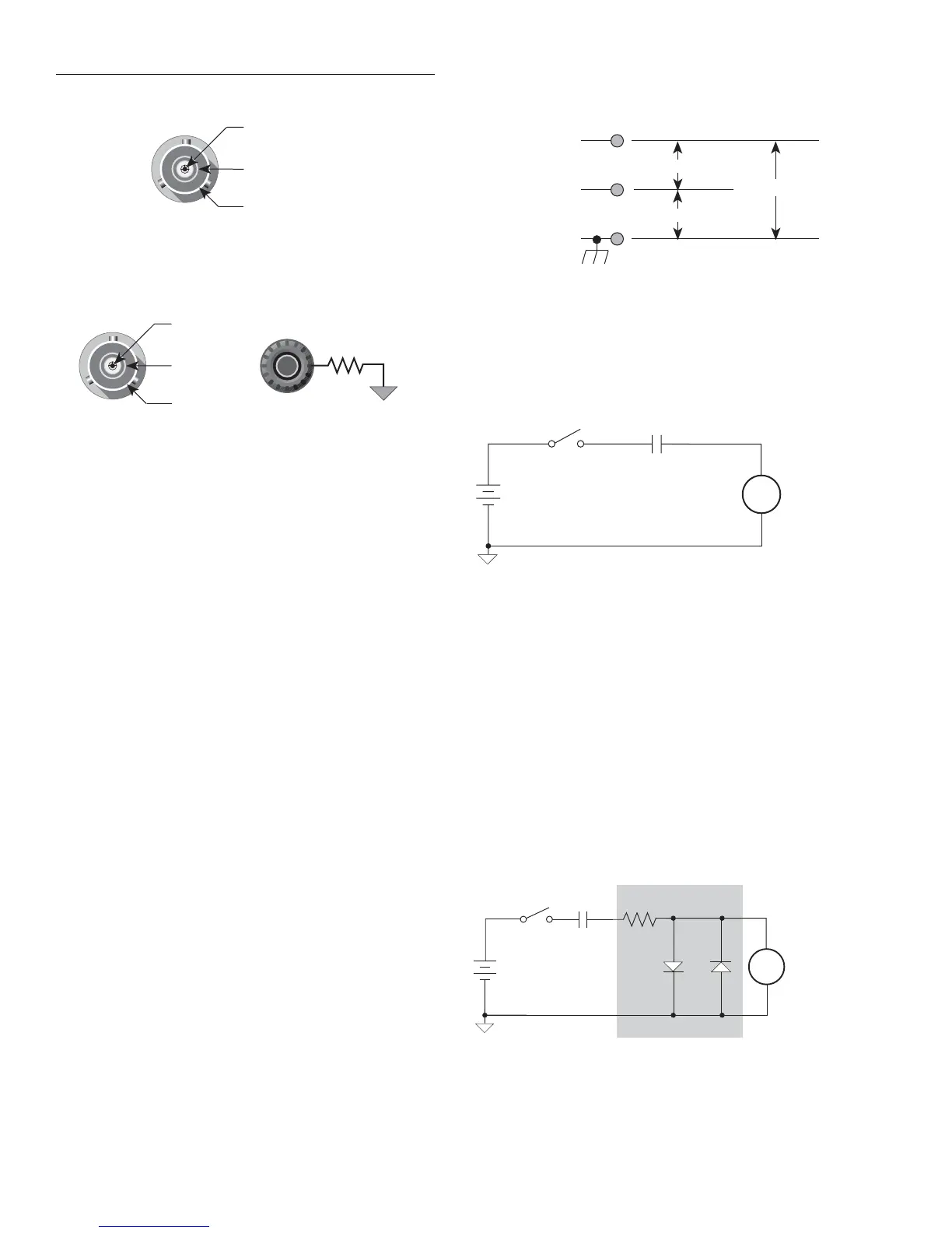
Maximum input levels — The maximum input levels to the
Model 6517A are summarized in Figure 2-6.
WARNING
The maximum common-mode input
voltage (the voltage between input low
and chassis ground) is 500V peak. Ex-
ceeding this value may create a shock
hazard.
CAUTION
Connecting PREAMP OUTPUT, COM-
MON, or 2V ANALOG OUTPUT to
earth while floating the input may dam-
age the instrument.
Input protection — The Model 6517A incorporates protec-
tion circuitry against nominal overload conditions. However,
a high voltage (>250V) and resultant current surge could
damage the input circuitry. A typical test circuit to measure
the leakage current of a capacitor is shown in Figure 2-7.
When Switch S is closed, an initial surge of charging current
will flow and the high voltage will be seen across the input
of the Model 6517A.
Adding a resistor and two diodes (1N3595) as shown in Fig-
ure 2-8 will provide considerable extra protection. The resis-
tor must be large enough to limit the current through the
diodes to 10mA or less. It must also be large enough to with-
stand the supply voltage. The protection circuit should be en-
closed in a light-tight conductive shield.
This same protection circuit is useful when measuring the in-
sulation resistance of films or high-voltage cables. Without
such added protection, a pinhole or other defect could cause
an arc, destroying the electrometer input.
Input High
Input Low
INPUT
250V PEAK
Chassis Ground
Volts, Amps, Ohms & Coulombs
Input High
Guard
INPUT
250V PEAK
Chassis
Ground
Volts only
COMMON
1Ω
Input Low
A. Unguarded (GUARD off)
B. Guarded (GUARD on)
Figure 2-5
Input connector configurations
Figure 2-6
Maximum input levels
Input High
Input Low
Max Input Signal *
500V Peak
Chassis Ground
500V Peak
* Max Input Signal - 250VRMS, DC to 60Hz sine wave
(10 seconds maximum in mA ranges).
Capacitor
Under Test
S
V
6517A
Ammeter
A
Figure 2-7
Capacitor test circuit without protection
Protection Circuit
HI
6517A
Ammeter
LO
Capacitor
Under Test
S
V
D1 D2
A
R
Figure 2-8
Capacitor test circuit with protection

 Loading...


