Front Panel Operation
2-55
2.11.3 External feedback procedure
Use the following procedure to operate the Model 6517A in
the external feedback mode.
1. Connect the feedback element between the PREAMP
OUT terminal and the Input High terminal.
2. Select the volts (V) function.
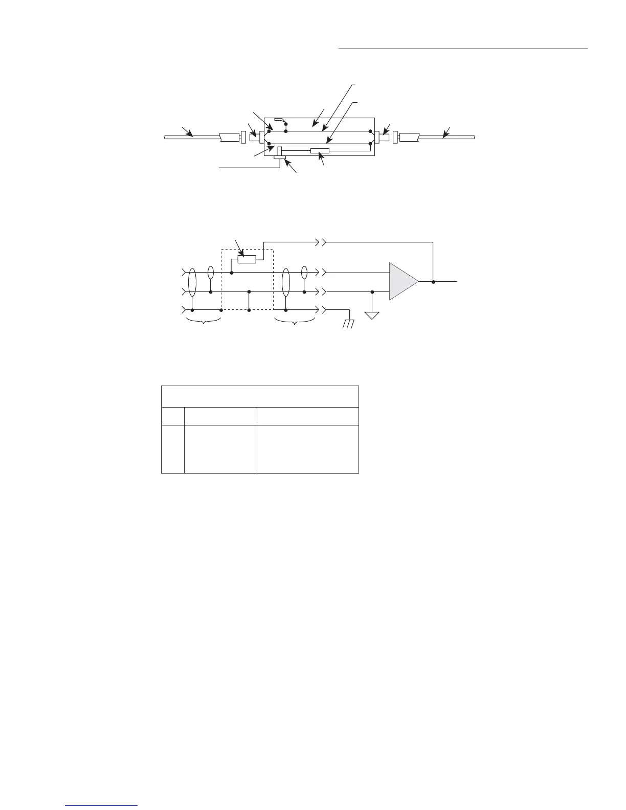
B. Equivalent Circuits
Preamp Out
Solder Lug
To 6517A
input
6517A Input
Amp
Input LO (Inner Shield)
To Preamp Out
Feedback Element
GND
+
-
Input HI (Center Conductor)
From Signal
GND
HI
LO
S
7078-TRX-3
Cable
HI
LO
2
To Ranging
Amp and A/D
5
3
2
4
1
A. Construction
HI
LO
Shielded
Fixture
237-ALG-2
Cable
Feedback
Element
Parts List
Item Description
MFR Part Number
1 Shielded Fixture
2 Female Triaxial
3 Banana Jack
4 Triaxial Cable
5 Triaxial Cable
Pomona #2390
Keithley 7078-TRX-TBC
Keithley BI-9-2
Keithley 237-ALG-2
Keithley 7078-TRX-3
Figure 2-43
Shielded fixture construction
3. Select external feedback as follows:
E. Press CONFIG V to display the CONFIGURE DCV
menu.
F. Place the cursor on EXT-FDBK and press ENTER.
G. Place the cursor on ON and press ENTER.
H. Use the EXIT key to back out of the menu.
4. The display will shown the voltage measured at the out-
put of the input preamplifier (PREAMP OUT).

 Loading...


