Front Panel Operation
2-33
2.7.1 Resistance measurements
The Model 6517A can make resistance measurements up to
10
17
Ω using the force voltage measure current (FVMI) tech-
nique. From the known sourced voltage and measured cur-
rent, the Model 6517A calculates and displays the resultant
resistance (R = V/I). The V-Source level can be set automat-
ically by the Model 6517A or it can be manually set by the
user.
The following steps summarize the basic steps to measure re-
sistance:
WARNING
Make sure the V-Source is in standby. In
standby, the OPERATE indicator is off.
The OPER key toggles the V-Source be-
tween standby and operate.
NOTE
To ensure proper operation, always enable
zero check ("ZeroCheck" displayed) be-
fore changing functions (V, I, R, or Q).
The Z-CHK key controls zero check.
1. Enable zero check by pressing Z-CHK.
2. Select RESISTANCE from the MEAS-TYPE selection
of the ohms configuration menu. The ohms configura-
tion menu is accessed by pressing CONFIG and the R
(see paragraph 2.7.3 for details).
NOTE
Step 2 can be skipped if the instrument is
already in the resistance measurement
mode.
3. Select the V-Source adjustment mode. With AUTO V-
Source selected, the instrument will automatically select
the optimum V-Source value (40V or 400V) for the mea-
surement range. With MANUAL V-Source selected, you
select the V-Source range and value. The V-Source ad-
justment mode is selected from the VSOURCE item of
the CONFIGURE OHMS menu. See paragraphs 2.7
(Auto V-Source) and 2.7.3 (VSOURCE) for details.
4. Connect the resistance to be measured to the Model
6517A. Figure 2-31 shows typical connections while
Figure 2-32 shows connections using the Model 8002A
High Resistance Test Fixture.
NOTE
The connections in Figure 2-33 assume
that V-Source LO is internally connected
to ammeter LO. This internal connection
is controlled from the METER-CON-
NECT option of the CONFIGURE V-
SOURCE menu (see paragraph 2.9.1).
This LO-to-LO connection can instead be
made by using an external cable to connect
V-Source LO to ammeter LO.
5. Select the ohms function by pressing the R key.
6. If the manual V-Source adjustment mode is selected, use
the , , and the VOLTAGE SOURCE ▲ and ▼
keys to set the voltage level. The V-Source range can be
changed from the RANGE item of the CONFIGURE V-
SOURCE menu. See paragraph 2.9.2 for details on set-
ting range and level for the V-Source. Note that you will
not be able to adjust the V-Source if AUTO V-Source is
selected.
WARNING
To avoid a possible shock hazard, do not
use a voltage level that exceeds the max-
imum input voltage rating of the test fix-
ture. For example, the maximum input
voltage to the Model 8002A High Resis-
tance Test Fixture must not exceed
200V peak.
7. Use the ▲ and ▼ RANGE keys to select the resistance
measurement range, or select AUTO range. Note that
with AUTO range selected, the instrument will not go to
the 2TΩ, 20TΩ and 200TΩ ranges.
NOTE
For optimum accuracy, leakage currents in
the test fixture can be cancelled by per-
forming REL on the current component of
the measurement. To cancel leakage cur-
rent, perform “Cancelling Test Fixture
Leakage Current” which follows Step 9 of
this procedure.
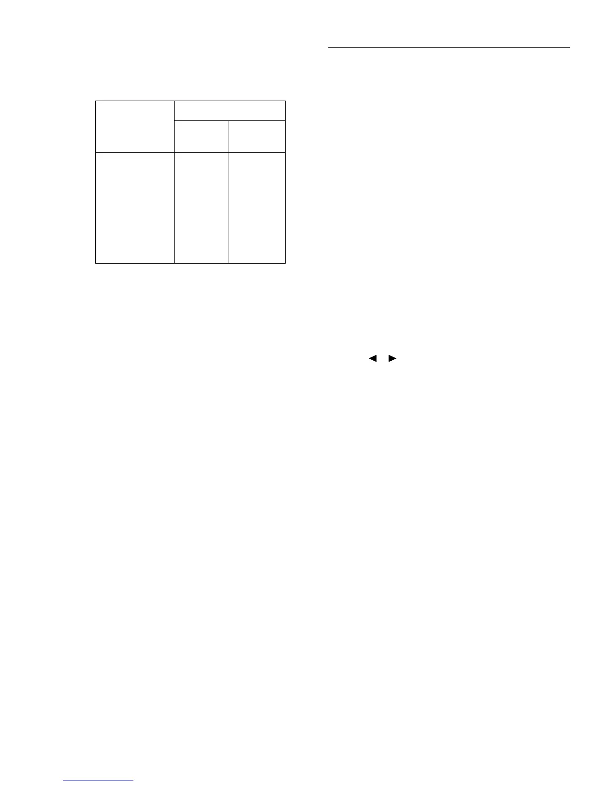
Table 2-11
Ohms reading ranges and AUTO V-Source
Reading range
AUTO V-Source
Test
voltage
Amps
range
200kΩ – 2MΩ
2MΩ – 20MΩ
20MΩ – 200MΩ
200MΩ – 2GΩ
2GΩ – 20GΩ
20GΩ – 200GΩ
200GΩ – 2TΩ
2TΩ – 20TΩ
20TΩ – 200TΩ
40V
40V
40V
40V
40V
40V
400V
400V
400V
200µA
20µA
2µA
200nA
20nA
2nA
2nA
200pA
20pA

 Loading...


