Front Panel Operation
2-34
8. Disable zero check by again pressing Z-CHK and press
OPER to source voltage to the DUT.
NOTE
A flashing VOLTAGE SOURCE OPER-
ATE LED indicates that the V-Source has
gone into current limit. The programmed
voltage is not being applied to the load. In
this situation, try using a lower voltage for
the measurement.
9. Take the reading from the display.
WARNING
Place the V-Source in standby before
making or breaking connections to the
test fixture or DUT.
Red
Black
6517A
Shield (Optional)
R
X
Measured
Resistance
LO connected
to shield
CAUTION:FOR CONTINUED PROTECTION AGAINST FIRE HAZARD,REPLACE FUSE WITH SAME TYPE AND RATING.
CAUTION:FOR CONTINUED PROTECTION AGAINST FIRE HAZARD,REPLACE FUSE WITH SAME TYPE AND RATING.
WARNING:NO INTERNAL OPERATOR SERVICABLE PARTS,SERVICE BY QUALIFIED PERSONNEL ONLY.
WARNING:NO INTERNAL OPERATOR SERVICABLE PARTS,SERVICE BY QUALIFIED PERSONNEL ONLY.
237-ALG-2
Cable
INPUT
250V PEAK
COMMON
TRIGGER
LINK
IN OUT
!
LINE RATING
90-134VAC
180-250VAC
50, 60, 400HZ
55VA MAX
LINE FUSE
SLOWBLOW
1/2A, 250V
IEEE-488
(CHANGE IEEE ADDRESS
WITH FRONT PANEL MENU)
PREAMP OUT
250V PEAK
V SOURCE
LO HI
Note: V-Source low internally
connected to electrometer
low.
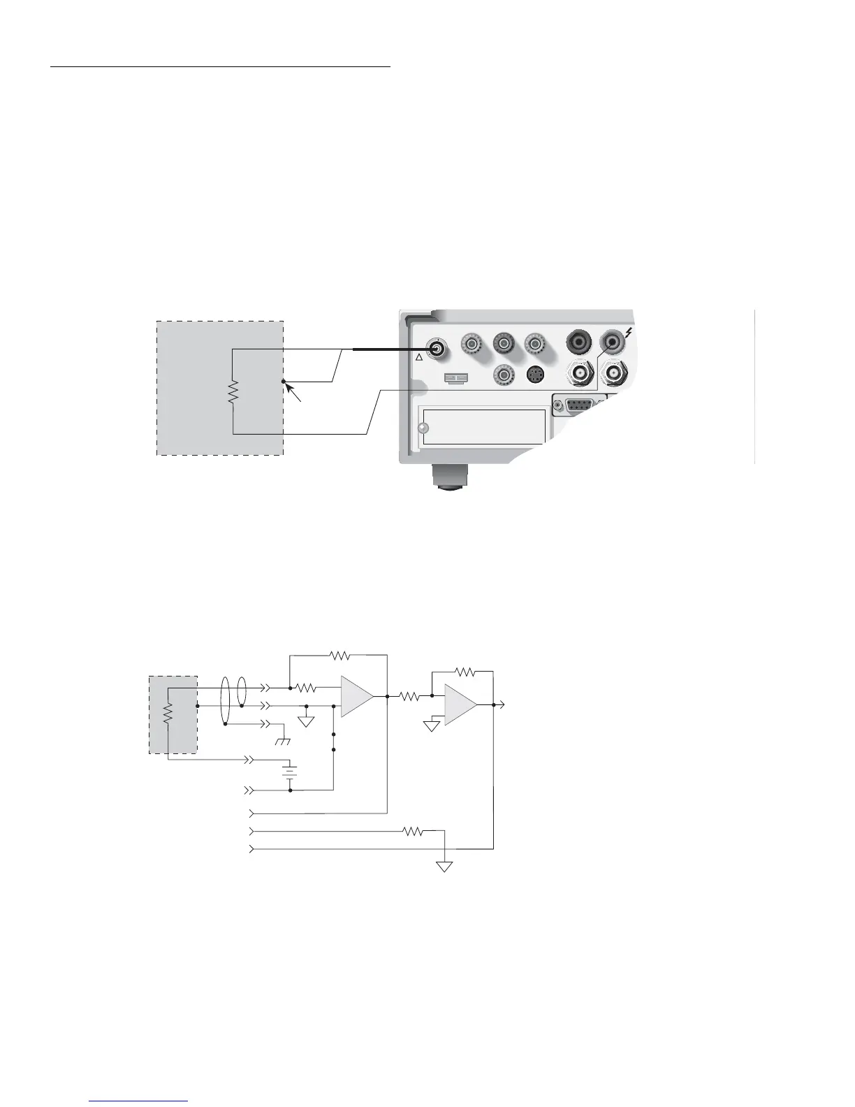
A) Connections
A. Connections
B. Equivalent circuit
Figure 2-31
Typical connections for resistance measurements
To A/D
Converter
S
HI
LO
Output
+
-
PREAMP OUTPUT
S
COMMON
2V ANALOG OUTPUT
+
-
S
Ranging
Amp
R
X
Input
Amplifier
Triax
Input
R
F
V
Source
B) Equivalent Circuit
Meter
Connect
Relay
1Ω

 Loading...


