Front Panel Operation
2-11
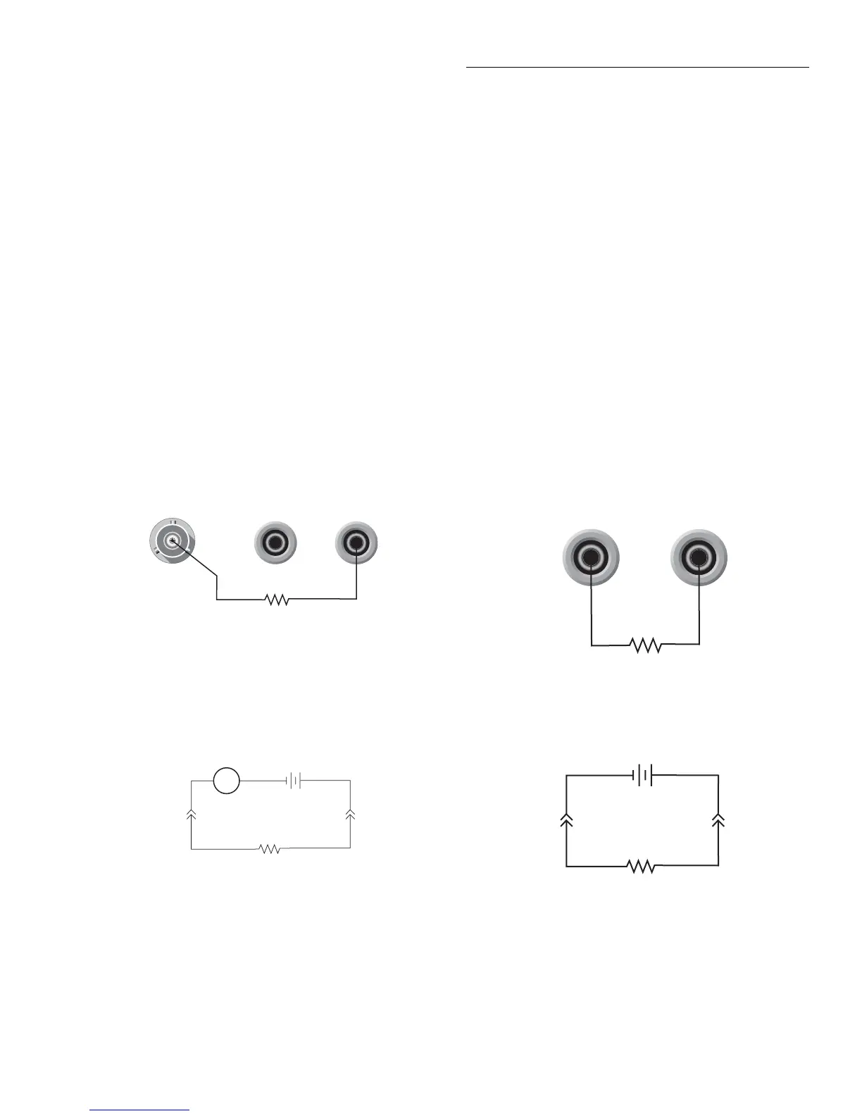
2.4.2 High-resistance meter connections
The Model 6517A uses the Force Voltage Measure Current
(FVMI) configuration to measure resistance. From the
known voltage and measured current, the resistance is calcu-
lated (R = V/I) and displayed.
The resistance to be measured is connected to the center con-
ductor of the INPUT triax connector and the V SOURCE
OUT HI binding post as shown in Figure 2-9A. This config-
uration assumes that V-Source LO is internally connected to
ammeter LO via the METER-CONNECT option of the
CONFIGURE V-SOURCE menu structure (see paragraph
2.9.1). The equivalent circuit for this configuration is shown
in Figure 2-9B.
WARNING
The maximum common-mode voltage
(the voltage between V-Source/Elec-
trometer LO and chassis ground) is
500V peak. Exceeding this value may
create a shock hazard.
2.4.3 Voltage source output connections
The voltage source output is accessed at the rear panel V
SOURCE OUT HI and LO binding posts as shown in Figure
2-10A. Using these terminals simply places the independent
V-Source in series with the external circuit (RL) as shown in
Figure 2-10B.
The V-Source can also be used be with the Electrometer to
form the Force Voltage Measure Current (FVMI) configura-
tion as shown in Figure 2-9. This configuration is used for re-
sistance measurements (see paragraph 2.4.2) and current
measurements. For these measurements, V-Source LO and
ammeter input LO can be connected internally via the
METER-CONNECT option of the CONFIGURE V-
SOURCE menu (see paragraph 2.9.1).
WARNING
The maximum common-mode voltage
(the voltage between voltage source low
and chassis ground) is 750V peak. Ex-
ceeding this value may create a shock
hazard.
A. Basic connections
B. Equivalent circuit
Figure 2-9
Force voltage measure current
INPUT
250V PEAK
HI
LO
V SOURCE
OUT
Note: V-SOURCE LO connected to ammeter input LO
via METER-CONNECT option of CONFIGURE
V-SOURCE Menu.
R
V-Source
R
HIHI
A
LO
Ammeter
Figure 2-10
V-source output
HI
LO
V-Source Out
V-Source
R
L
LO HI
A. Basic connections
B. Equivalent Circuit
R
L

 Loading...


