MAINTENANCE
3-64 WB140-2N, WB150-2N
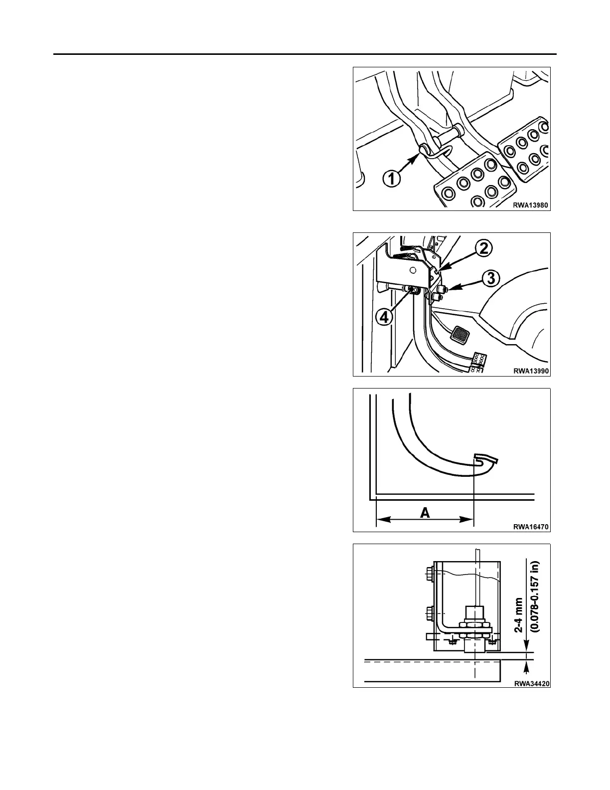
CHECKING AND ADJUSTING BRAKE
PEDAL STROKE
Perform this check when working on adjusting the brake pedal stroke to
eliminate or prevent any problems.
To check and adjust the brake pedal stroke, proceed as follows:
1. Insert connection pin (1) in order to couple the pedals.
2. By adjusting the end-of-stroke rubber pads (2), position the pedals
in correspondence with measure “A”= 325 mm (12.8 in); secure the
pads in this position. (Use a 13 mm wrench).
3. Lower the pedals to measure “A” 306 mm (12 in); adjust position
of microswitches (3) by bringing them near the pedals and lock
them. (Use a 17 mm wrench).
4. Again, lower the pedals to measure 294 mm (11.6 in) at “A” and
adjust brake pump rods (4) until they touch the pumping pistons,
lock them in this position. (Use a 22 mm wrench).
ADJUSTING AUTOMATIC RETURN OF
FRONT BUCKET TO THE DIGGING POSI-
TION
The device for automatic return of front bucket to the digging position
automatically brings the front bucket to loading position when it is low-
ered to the ground. The sensor is positioned on right dumping cylinder
and determines the horizontal position of the bucket in relation to the
ground after bucket dumping control has reached end of stroke and elec-
tromagnet of the distributor rod has been operated (See “FRONT END
LOADER CONTROLS” on page 2-16).
The sensor must be positioned at a distance of 2-4 mm (0.078-0.157 in)
from the sliding rod.
 Loading...