Home
LeCroy
Test Equipment
WaveSurfer 400 Series
LeCroy WaveSurfer 400 Series User Manual
4
of 1
of 1 rating
178 pages
Give review
Manual
Specs
To Next Page
To Next Page
To Previous Page
To Previous Page
Loading...
6-32
Maintenance
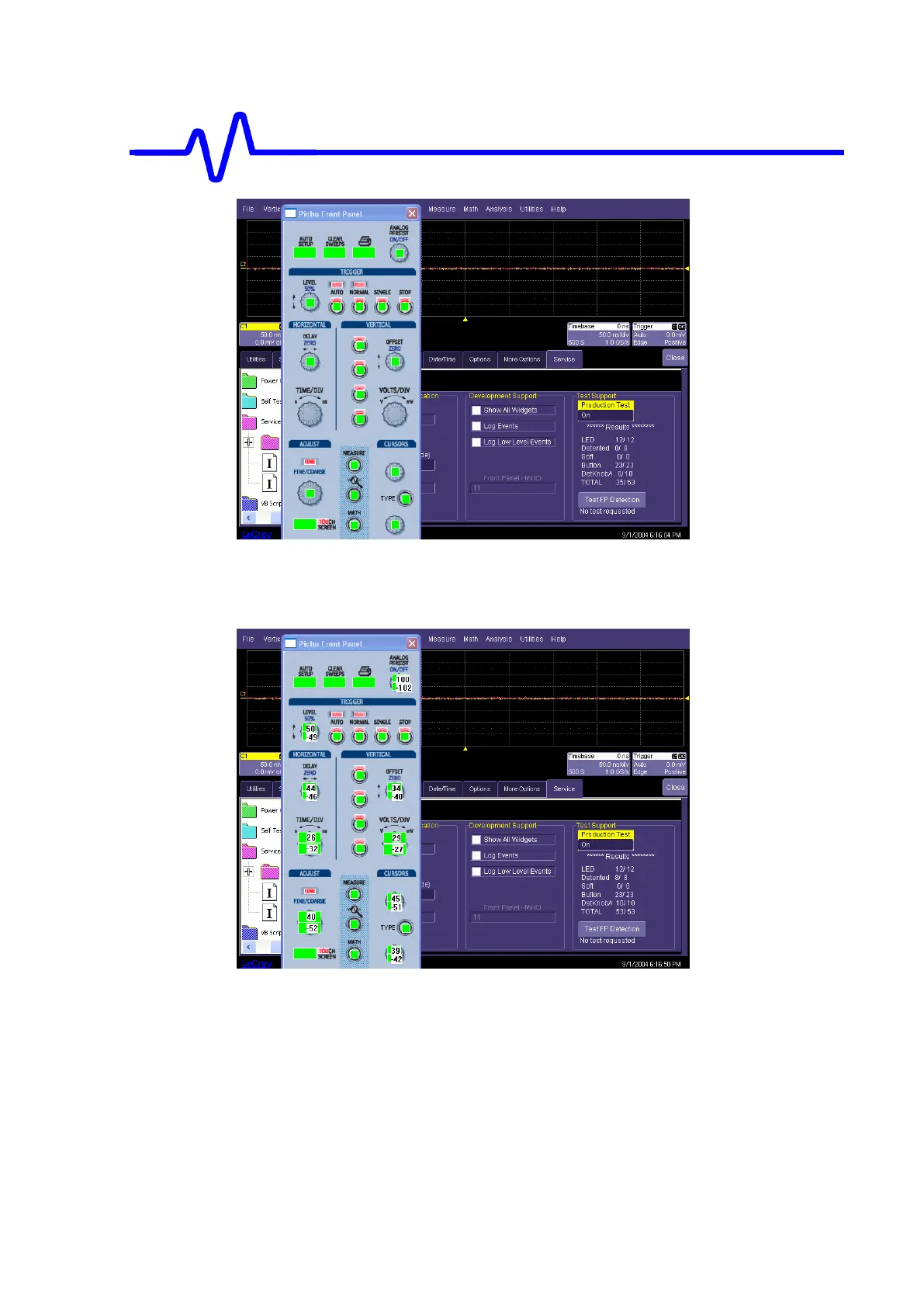
Continue until all buttons and knobs have been tested, the total should indicate that all
needed items were pressed or turned. .
Select Production test and then off to turn off the test. The front panel LED’s will be left in
an abnormal state. This will be corrected when either the functions are used or when the
application is restarted.
117
119
Table of Contents
Table of Contents
3
Read this First
9
Warranty
9
Warranty and Product Support
9
Product Assistance
9
Maintenance Agreements
9
Staying up to Date
10
Service and Repair
10
How to Return a Product
10
What Comes with Your Scope
10
General Information
11
Product Assistance
11
Installation for Safe and Efficient Operation
11
Operating Environment
11
Safety Symbols
11
Power Requirements
13
Cleaning and Maintenance
13
Specifications
15
Vertical
15
Triggering System
15
Standard Triggers
15
Optional SMART Triggers
16
Documentation and Connectivity
16
Measure, Zoom, and Math Tools
17
Automatic Setup
17
Setup and Waveform Storage
17
Outputs
17
Environmental and Safety
18
Physical Dimensions
18
General
18
Warranty & Calibration
18
Theory of Operation
19
System Block Diagram
19
Main Board
20
Front End
21
Analog to Digital Converter
23
Trigger
24
Time Base
27
Calibrator
28
Scan DAC
28
Main Board Control
28
Computer
29
Operating System
29
Memory
29
Interfaces
29
Storage Devices
29
Video Port
29
PCI Card
30
PCI Interface
30
Local Bus for Acquisition
31
Control
31
Acquisition Data
31
Dallas Onewire Interface
31
Audio Amplifire
31
Front Panel
31
Key Board
32
Panel Board
32
Encoders
32
Touchscreen Interface
32
Display and Touchscreen
33
Color LCD Module
33
Backlight Inverter
33
Touch Screen
33
LVDS Receiver
33
Power Supply
34
Input Voltages
34
Output Voltages
35
Basic Operation
35
Pre-Converter
35
Main Converter
35
House Keeping Power Supply
35
5VDIG and 3.3V DC/DC(Daughter Board)
35
5VANA and 2.5V DC/DC (Daughter Board)
36
And 12V DC/DC (Daughter Board)
36
Filter Circuits (Daughter Boards)
36
Connector Assignments
36
Output Voltage Adjustment Range
39
5VSB Standby Supply Rail
39
Performance Verification
41
Introduction
41
List of Tested Characteristics
41
Calibration Cycle
41
Test Equipment Required
42
Test Records
42
Turn on
42
Input Impedance
43
Channel Input Impedance
43
External Trigger Input Impedance
47
Leakage Current
49
Channel Leakage Current
49
External Trigger Leakage Current
52
Peak-Peak Noise Level
54
DC Accuracy
56
Positive DC Accuracy
56
Negative DC Accuracy
59
Offset Accuracy
60
Positive Offset Accuracy
60
Negative Offset Accuracy
62
Bandwidth
63
Description
63
Trigger Level
68
Description
68
Channel Trigger at 0 Division Threshold
68
Channel Trigger at +2.5 Divisions Threshold
71
Time Base Accuracy
74
Description
74
Clock Verification Procedure
74
Introduction
87
Safety Precautions
87
Anti-Static Precautions
87
Software Update Procedure
87
Installing New X-Stream DSO Application Software
88
Software End User License Agreement
89
Installing Device Drivers
94
Restoring the Operating System
95
Software Options
100
Changing Software Option Key
100
Board Exchange Procedure
101
PCI Board Exchange Procedure
101
Hard Drive Replacement Procedure
101
Required Items
101
Preparation of Host Machine
101
Copying Necessary Files to Share Them through Network
102
Creating a Network-Ready Startup Disk
103
Updating the Hard Disk (through a Network)
106
Setup at the First Startup
108
Validating the Software
110
Initialization of Panel Setup
110
BIOS Setting
111
Battery Exchange Procedure
114
Update BIOS
114
Equipment and Spare Parts Recommended for Service
115
Test Equipment Required
115
Wavesurfer Spare Parts
115
Service Menu
116
Accessing Service Menu
116
Mainframe Tests
117
Front Panel Test
117
Calibration Procedures
119
System Power Supply Calibration Procedure
119
Touch Screen Calibration Procedure
121
Front/Acq System Adjustments
123
Internal Reference Voltage Adjustment
123
Front End Adjustment
124
TDC Adjustment
127
Trigger Delay Adjustment
127
Trigger Hysteresis Adjustment
128
Event Trigger Delay Adjustment
128
Odd Path Adjustment
129
Trigger Analog Time Adjustment
130
Adjustment of Time Difference between Channels
132
Speaker Volume Adjustment
133
Troubleshooting and Flow Charts
133
Introduction
133
Repair Level
133
Initial Troubleshooting
134
Power Supply Problem
136
No Display (Internal or External)
137
Internal Display Problem
139
Boot up Sequence
140
Front Panel Controls or Touch Screen Does Not Operate
141
Timebase Problem
145
Remote Control Problem
146
Vertical Accuracy Problem
147
Bandwidth Problem
148
Line Trigger Problem
149
Mechanical Parts & Removal
151
Over All Replaceable Parts
151
Over All Block Diagram
153
Disassembly Flow Charts
154
OUTER Replaceable Parts
155
REAR & SIDE Replaceable Parts
155
FRONT Panel Assy
164
FRONT Bezel Assy
164
Spare Parts
165
4
Based on 1 rating
Ask a question
Give review
Questions and Answers:
Need help?
Do you have a question about the LeCroy WaveSurfer 400 Series and is the answer not in the manual?
Ask a question
LeCroy WaveSurfer 400 Series Specifications
General
Brand
LeCroy
Model
WaveSurfer 400 Series
Category
Test Equipment
Language
English
Related product manuals
LeCroy WAVESURFER
128 pages
LeCroy WavePro 7100A
437 pages
LeCroy WavePro 7200A
437 pages
LeCroy WaveAce series
106 pages
LeCroy Waverunner2 Series
155 pages
LeCroy Waverunner2 LT584M
155 pages
LeCroy Waverunner2 LT374M
155 pages
LeCroy WaveJet 300A series
67 pages
LeCroy WaveRunner XI Series
233 pages
LeCroy Waverunner2 LT584 Series
155 pages
LeCroy Waverunner2 LT264 Series
155 pages
LeCroy Waverunner2 LT372 Series
155 pages

 Loading...