4.6 Display and Touchscreen
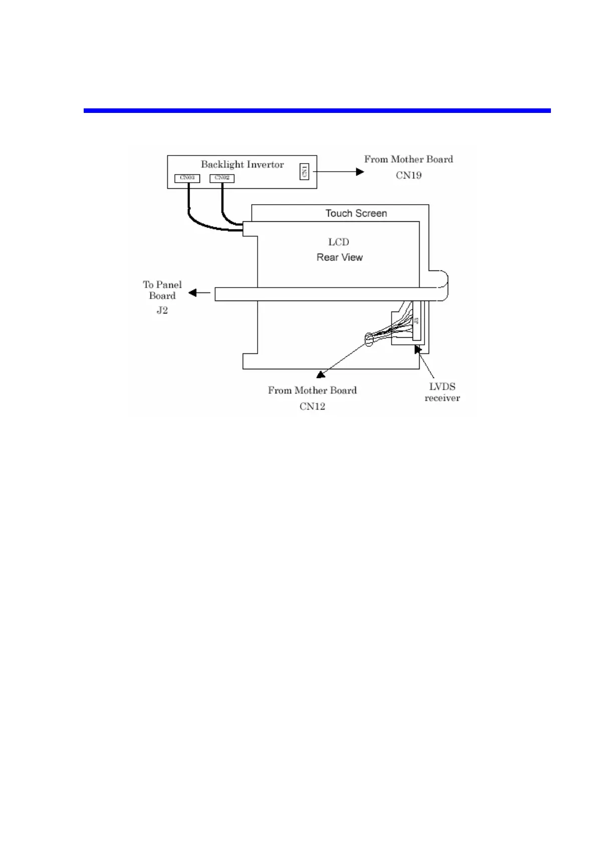
Figure 4-12 Display & Touchscreen Block Diagram
4.6.1 Color LCD Module
The display module is an SHARP TFT (thin film transistor) active matrix color liquid
crystal display (LCD) module comprising amorphous silicon TFT attached to each
signal electrode, a driving circuit and a backlight. The 26cm diagonal display area
contains 800x600 pixels (SVGA) and can display 262144 colors simultaneously.
4.6.2 Backlight Inverter
The inverter which supplies power to the LCD's backlight is supplied with +12V from
the Mother board, it then converts this to 1000-2000V AC to drive the CCFT (Cold
Cathode Fluorescent Tube). There is also a signal from the Mother board which
controls the On/Off of the backlight.
4.6.3 Touch Screen
The touch screen is a 4 wire resistive touch screen. It must be calibrated so that
software can determine where a touch corresponds to a position on the screen. This
calibration is done at four points and can be invoked through the Utilities menu.
4.6.4 LVDS receiver
Mother board has LVDS output for LCD. LVDS receiver receive the LVDS signal
from Mother board, it then converts this to 18bits RGB (each color has 6bits depthfor
input type of LCD module.
Theory of Operation 4-15

 Loading...