4-16 Theory of Operation
4.7 Power Supply
Do not touch any electric parts inside the power supplies during operation
as the primary side of the power unit has many high voltage portions to ground.
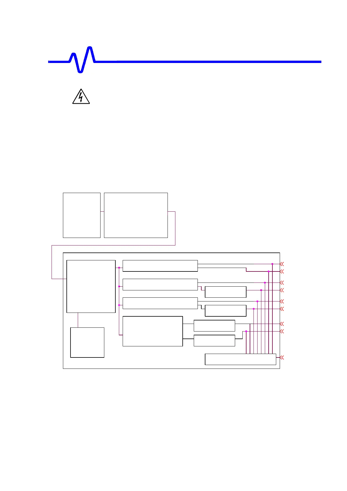
Power Supply Unit comprises of INLET BOARD, PFC BOARD and MAIN BOARD.
The INLET BOARD includes EMI Filters.
The PFC BOARD includes Pre-converter, which is operated Power Factor
Correction.
The MAIN BOARD includes Main Converter (off line), House Keeping Power
Supply, Post Converters, Filters, Power OK Generater circuit and internal Bias
Supply Circuits.
3.3V
House
keeping
Power
Supply
-5V
Main
Converter
5VDIG and 3.3V DC/DC
MAIN POWER BOARD
INLET
BOARD
-5V and -12V
Foward Converter
-12V
5VANA
2.5V
POWER_OK_GEN
PW_OK
Filter
(-12v)
Pre-Converter
PFC
9V
Filter
(-5v)
12V
Filter
(12v)
5VDIG
PFC BOARD
Filter
(5vANA)
EMI
Filters
5VANA and 2.5V DC/DC
9V and 12V DC/DC
Solid Line Blocks represent Daughter Boards.
Figure 4-13 Power Supply Block Diagram
4.7.1 Input Voltages
The power supply supports a wide ranges of inputs, 90-132 V AC (45-65HZ, 360-
440Hz) and 90-264V AC (45-65Hz) are allowed.

 Loading...