4-2 Theory of Operation
4.2 Main Board
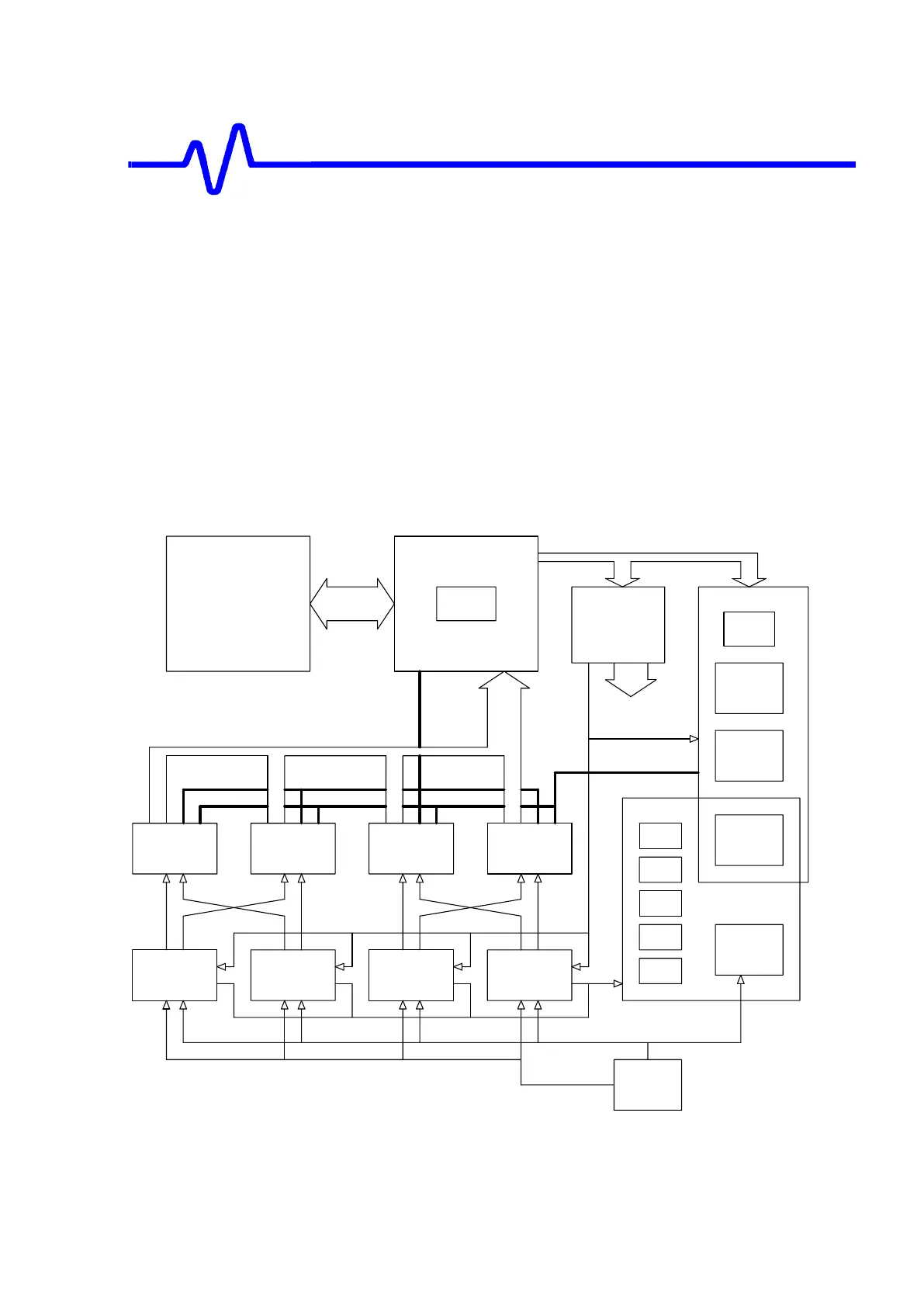
The main board is divided into the following sections:
• Front End
Based on high impedance buffer, variable gain amplifier and differential
amplifiers.
• Analog to Digital Converter
Based on the HAM631 and the relay switchyard to combine the input channels.
• Trigger
Based on the Hybrids HTR420 discriminator & MST429A smart trigger.
• Time Base
Based on the MCG426 clock generator & MTB411A controller.
• Calibrator
• SCAN DAC
• Main Board Control
MAIN BOARD
CONTROL
TDC
D0-7
AC Calibration
HTR420
32bit Bus
8bit Bus
Calibrator
D0-31
D24-31
HTR420
TIME BASE
D16-23
CH1
ADC
System
SCAN DAC
HTR420
D8-15
Zo=50ohms
CH1
FRONT
END
CH4
FRONT
END
Serial Bus
HTR420
CH3
FRONT
END
TRIGGER
PCI Card
CH2
FRONT
END
EXT
input
HTR420
DC Calibration
MAM633
Control
CH4
ADC
System
MST429A
PCI Bus
Time Base Control
CH3
ADC
System
MCG426
FPGA
MTB411A
Serial Bus
CH2
ADC
System
Trigger signal
uATX Board
Analog Control
Figure 4-2 Acquisition Block Diagram

 Loading...