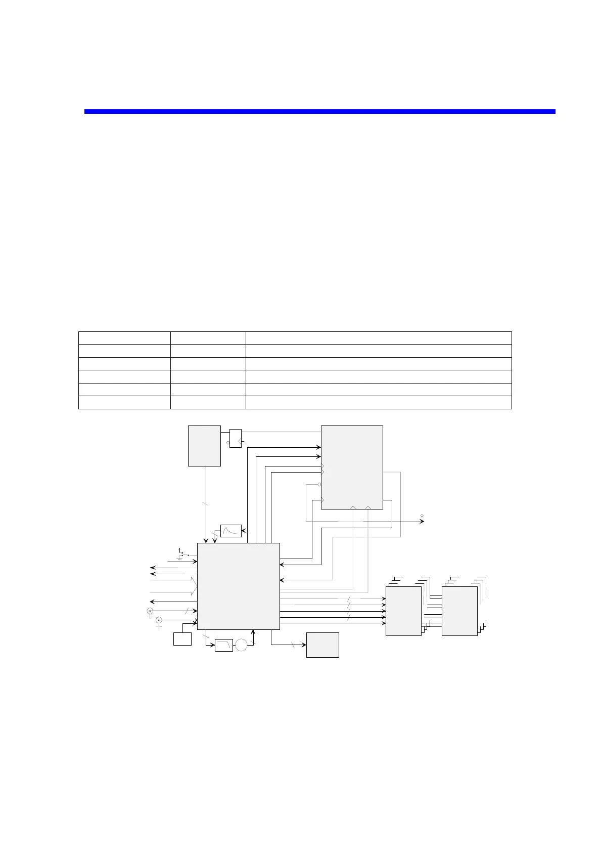
4.2.4 Time Base
The time base includes four circuits:
• MCG426: generates sampling clocks: 12.5 MHz up to 2GHz
generates clocks for the MTB411
interleaves sampling clocks to increase sampling rate and memory
depth.
• MTB411A: Time Base System
Trigger circuitry
Main oscillator circuitry
Frequency divider for a Probe Calibrator
• TDC: Time to Digital Converter interpolator and Real Time computation
• MST429A: generates main trigger signal for Time Base system.
Analog Control voltage
Circuit name signal level Signal name
MST REF1 +/-4V Reference signal for analog time of Smart trigger
MST REF2 +/-4V Reference signal for analog time of Smart trigger
MST REF3 +/-4V Reference signal for analog time of Smart trigger
MST REF4 +/-4V Reference signal for analog time of Smart trigger
TDC ADJ 0 to +4V TDC gain control signal
MTB 411
MST 429
MCG 426
HSH & ADC
SHCK_A
SHCK_B
SHCK_C
SHCK_D
2
2
2
2
MCK
TRIG
TRIG
2
Peak
Detect
MPD
10 MHz
Reference
INTREF
PHDET
VCO
VCO2G PDCK
2
2
2
RAMPST
R
A
M
PS
TRTTRT
to trigger selection
SHCK_A
SHCK_B
SHCK_C
SHCK_D
Q
Q
D
ENABLE TRIGEN
ITBUSY
MACQ
FDEND
FDCK
TR
IG
D
IT
C

 Loading...