Wiring the standard device
Basic devices in the power range 45 ... 55 kW
Motor connection
5
5.6
5.6.4
5.6-6
EDSVF9333V EN 3.0-06/2005
Features of the connection for motor temperature monitoring:
Terminals T1, T2
Connection
z PTC thermistor
– PTC thermistor with defined tripping temperature (acc. to
DIN 44081 and DIN 44082)
z Thermal contact (NC contact)
– Temperature switch as NC contact
Tripping point z Fixed (depending on the PTC/thermal contact)
z PTC: Rϑ
> 1600 Ω
z Configurable as warning or error (TRIP)
Notes z Monitoring is not active in the Lenze setting.
z If you do not use a Lenze motor, we recommend a PTC thermistor
up to 150°C.
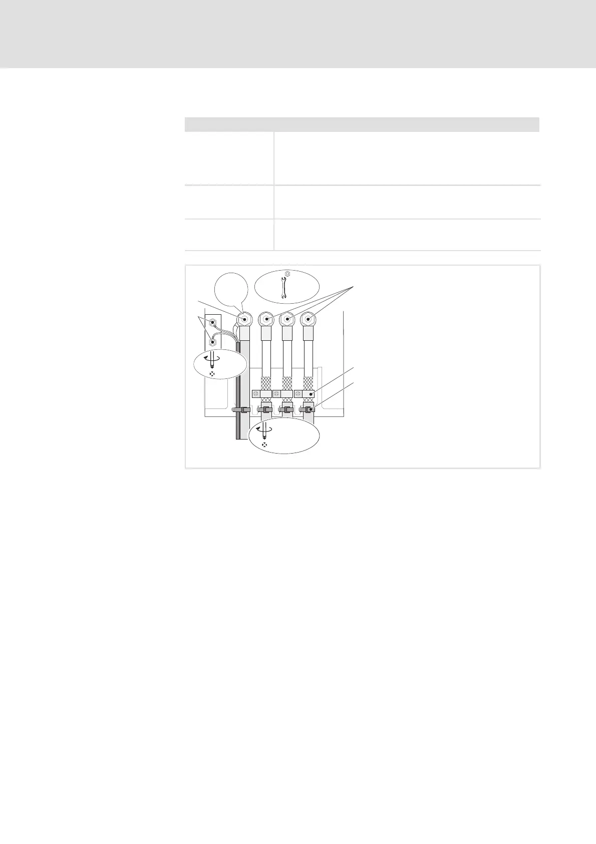
T1
T2
PE
U
VW
2
3
0
4
T1
T2
2.5 Nm
22.1 lb-in
U, V, W,
PE
M8
15 Nm
132 lb-in
1
M5x12
3 Nm (26.5 lb-in)
}
+
PE
9300std031
Fig. 5.6-4 Motor connection w ith PTC thermistor or thermal contact (NC contact)
PE stud
Connection of PE cable with ring cable lug
U, V, W
Connection of motor cable with ring cable lugs
Observe correct polarity. Observe maximum length of motor cable.
Shield clamps
Connect shields of motor cable with a surface as large as possible t o the
shieldsheetandfastenwithshieldclampsandM5×12mmscrews
Cable ties
Strain relief of motor cable
T1, T2 for motor temperature monitoring
Connection of cable for PTC thermistor or thermal contact (NC contact)
Connect shield with a surface as large as possible t o PE stud
 Loading...