Installing the basic device
Basic devices in the power range 75 ... 90 kW
Thermally separated mounting (push-through technique)
4
4.4
4.4.3
4.4-3
EDSVF9333V EN 3.0-06/2005
4.4.3 Thermally separated mounting (push-through technique)
For mounting in push-through technique, the drive controller of type
EVF93xx-EV. In addition, the mounting set for EJ0001 push-through
technique is required.
h
c1
c2
c3
c4
g
a1
a
d1
h
d2
d2
d2
d
b
b1
e1
e
L
9300vec118
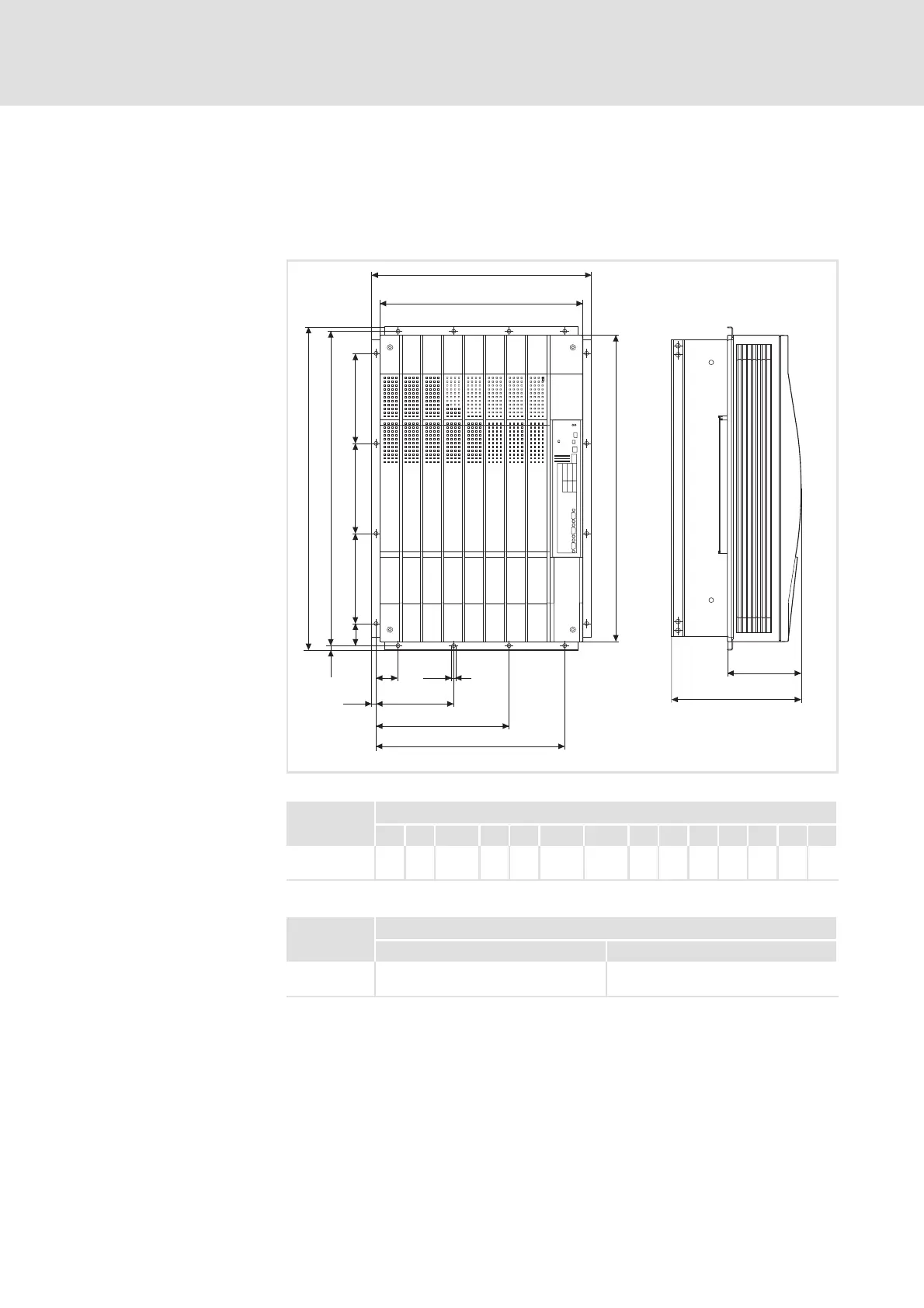
Fig. 4.4-2 Dimensions for thermally separated m ounting 75 ... 90 kW
9300 vector Dimensions [mm]
Type a a1 b b1 c1 c2 c3 d d1 d2 e
1)
e1 g h
EVF9332-EV
EVF9333-EV
488 450 718 680 49 172.5 295.5 698 49 200 285 164 9 10
1)
For a fieldbus module plugged onto X1, consider mounting space for connecting cables
9300 vector Dimensions [mm]
Type A1 b1
EVF9332-EV
EVF9333-EV
428.5 660
Dimensions
Mounting cutout in control
cabinet
 Loading...