Wiring the standard device
Control connections
With active ”safe standstill” function
5
5.9
5.9.2
5.9-4
EDSVF9333V EN 3.0-06/2005
ƒ For supplying the digital inputs (X5/E1 ... X5/E5, X5/ST1), a freely
assignable digital output (e. g. X5/A1) must be firmly applied to HIGH
level.
ƒ For supplying the analog inputs (X6/1, X6/2 and X6/3, X6/4), a freely
assignable analog output (e. g. X6/63) must be firmly applied to HIGH
level.
GND2 +24V+5 V
DIGOUT4
E5
A2 A3 A4 ST1
ST2
59
39
3k
47k
50mA
50mA
50mA
50mA
X5
28
E1 E2 E3 E4
3k
3k
3k
3k
3k
X11
K31K32 33 34
S1 S2
IN1 IN2
IN3
IN4
+
K
SR
A1
Z1
X3
GND1 GND1
X6
1
AIN1 AIN2 AOUT1 AOUT2
2
3
4
AOUTx AOUTx
1
3
24
10k 10k
7762
63
242R
1
2
3
4
5
6
100k
100k
100k
100k
3.3nF
9300vec135
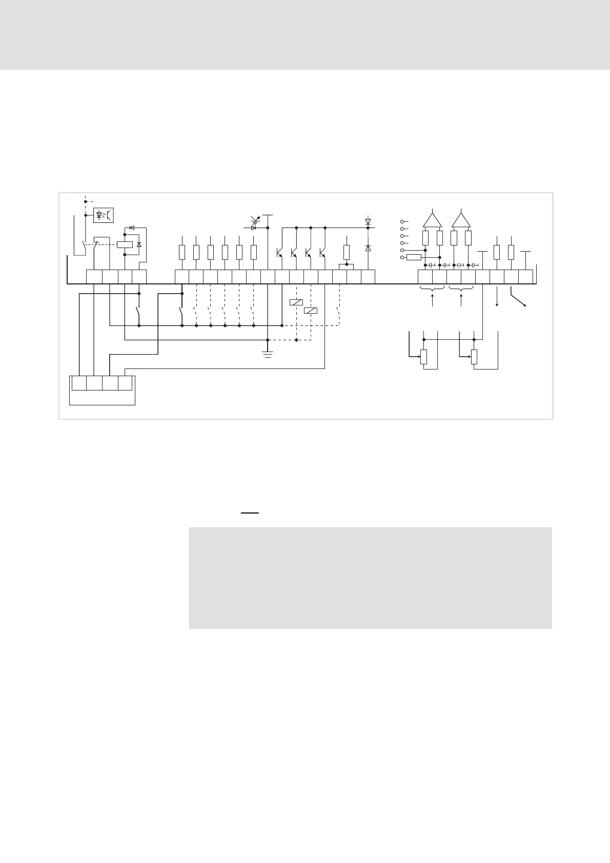
Fig. 5.9-2 Wiring of digital and analog inputs/outputs with active ”safe standstill” function
and internal voltage source
S1 Deactivate the pulse inhibit (1. disconnecting path)
S2 Enable the controller (2. disconnecting path)
Z1 Programmable logic controller (PLC)
The PLC accepts the automatic cyclic monitoring of the ”safe
standstill” function
X5/A4 Feedback via a digital output (e. g. DIGOUT4)
The min. wiring requirements for operation
Note!
If you load a basic configuration C0005 = xx1x (e.g. 1010 for
speed control with control via terminals), the following terminals
areswitchedtoafixedsignallevel:
ƒ Terminal X5/A1 to FIXED1 (corresponds to DC 24 V).
ƒ Terminal X6/63 to FIXED100% (corresponds to 10 V).
Supply via internal voltage
source
 Loading...