Physical Views Product Description
1 - 14 046-004667-00 A7™ Operating Instructions
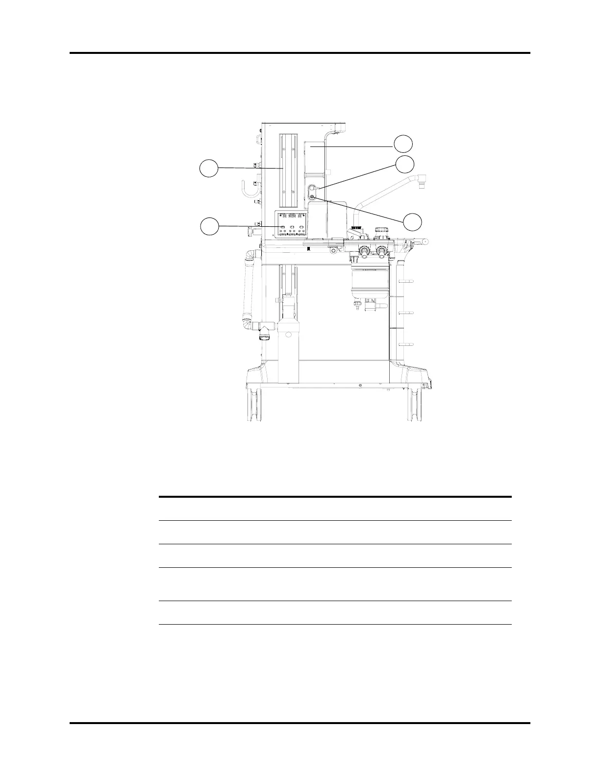
1.2.3 Main Unit (Left View)
FIGURE 1-4 Main Unit (Left View)
PART(S) DESCRIPTION
C1 Auxiliary O
2
/Air
Flowmeters
Auxiliary O
2
/Air Flowmeters for auxiliary O
2
/Air output
C2 Auxiliary O
2
/Air Gas
Outlet
Nozzle (barbed connector) for auxiliary O
2
/Air output. Combines
the auxiliary O
2
/Air flowmeters into a single output.
C3 Auxiliary O
2
Gas Power
Outlet
High pressure O
2
outlet (DISS connector) for connecting external
devices such as a jet ventilator.
C4 Rail Mount Enables mounting of patient monitors and most standard
attachment arms for other devices. Rail mounts are on both left and
right sides of the A7.
C5 Module slot AG module mentioned in this manual can be inserted into the slot
and identified.
C2
C3
C1
C4
C5

 Loading...