Home
Mindray
Diagnostic Equipment
DC-80A
Mindray DC-80A Service Manual
5
of 1
of 1 rating
305 pages
Give review
Manual
Specs
To Next Page
To Next Page
To Previous Page
To Previous Page
Loading...
9-
52
S
tructure
and
Assembly
/Disasse
mbly
No.
Device Name
Port
Descriptio
n
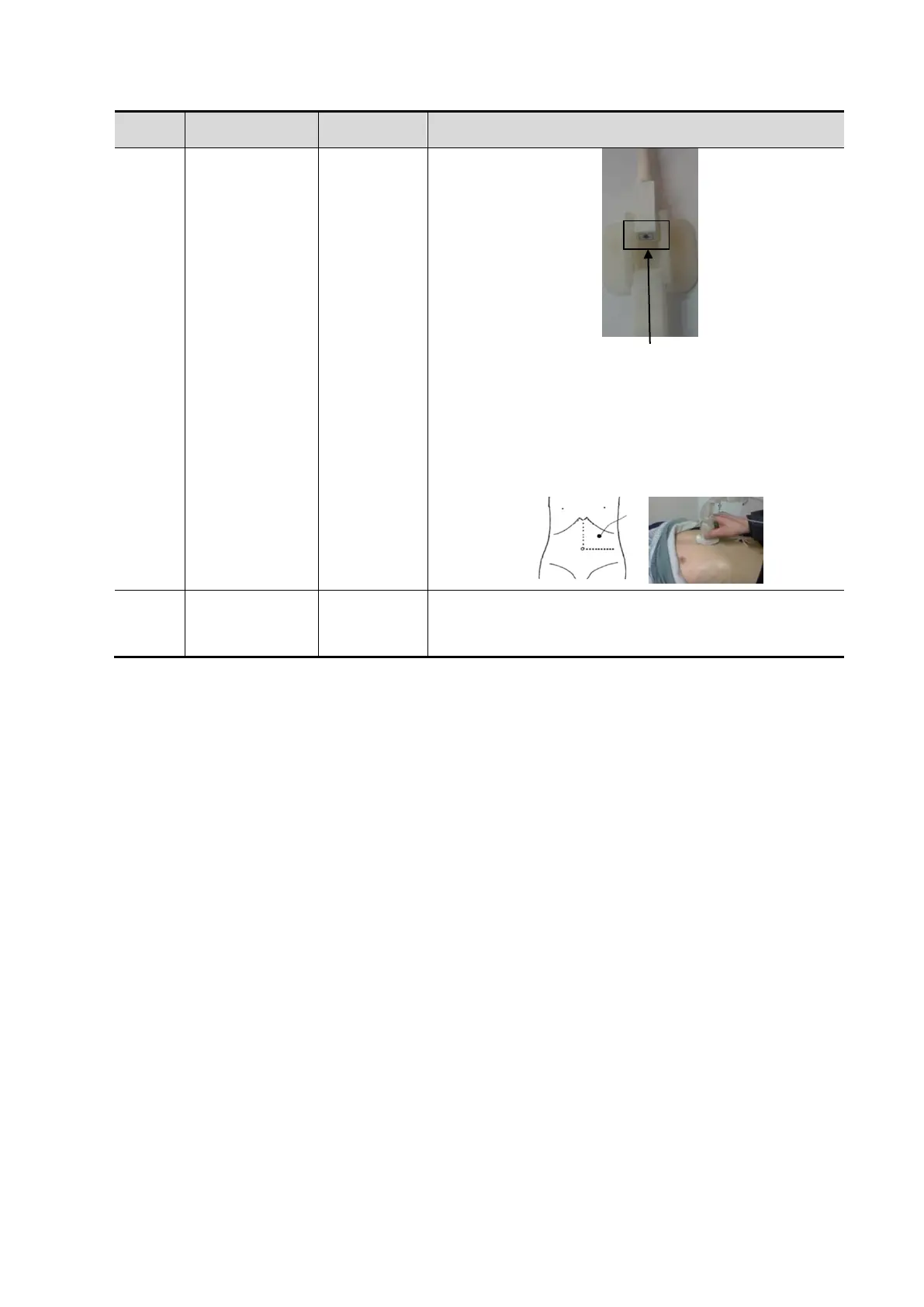
5.
Motion (abdo
men) sen
sor supp
ort: st
ick the sensor
support agai
nst the t
op lef
t of the p
atient
’
s
abdomen with
the me
dical plasters (
below l
eft
costa
l arch, rig
ht above t
he navel, t
he area where
the skin m
oves app
arently
with
the respirat
ion).
<9>
Magnetic
navigator
/
Place the
magnetic nav
igator
behind the
Ultrasoun
d
System. P
ower on the
navigator
to enabl
e the
positionin
g function.
Face downward
199
201
Table of Contents
Table of Contents
3
Revision History
9
Intellectual Property Statement
10
Applicable for
10
Statement
10
Responsibility on the Manufacturer Party
11
Customer Service Department
11
Safety Precautions
13
Meaning of Signal Words
13
Symbols
13
Meaning of Safety Symbols
13
Warning Labels
14
General Symbols
14
Safety Precautions
16
Electric Safety
16
Mechanical Safety
17
Personnel Safety
17
Other
17
Specifications
19
Overview
19
Intended Use
19
Introduction of each Unit
19
Peripherals Supported
28
Specifications
28
Dimensions & Weight
28
Electrical Specifications
28
Environmental Conditions
29
Monitor Specification
29
System Installation
31
Preparations for Installation
31
Electrical Requirements
31
Installation Conditions
32
Confirmation before Installation
33
Unpacking
33
Unpacking Process
33
Check
35
Installation of Main Unit
35
Open up the Monitor
36
Connecting the Power Cord
36
Powered by Battery
37
Equipotential Terminal
37
Connecting ECG
38
Installing Probe/Gel Holder
38
Connecting the Transducer
39
Installing Peripherals
40
Connecting the Footswitch
40
Installing a Graph / Laser Printer
41
Installing Video Printer
43
Position a Printer
44
Installing Barcode Scanner
44
System Configuration
45
Running the System
45
Enter Doppler
46
System Preset
47
Print Preset
48
Network Settings
48
Network Configuration
50
Security
51
DICOM/HL7 Preset
52
Check System Information
54
Product Principle
55
Hardware System Diagram
55
Ultrasound Front-End Unit
56
Probe Board
57
TR64 Board
58
CW Module
59
Engine Board
59
TEE Module
61
ECG Module
62
Ultrasound Back-End Unit
62
PC Module
63
GPU Module
63
Storage Device
63
Wireless Network Module
64
PC Carrier Board
64
IO Interface Module
65
Extension and Distribution
65
Video Extension Function
65
Audio Interface
66
SATA Interface
67
USB Distribution
67
Network Interface
68
PCIE Interface Distribution
68
Other IO Extension
68
Power Supply Unit
69
AC Connecting Board
70
AC-DC Module
70
To 12V Power Conversion Board
70
DC-DC Board
71
PHV Board
71
Time Sequence of Power-On
71
User Interaction Unit
72
Control Panel Assembly
72
Primary Display Assembly
73
Secondary Display Assembly
73
Function and Performance Checking Method
75
Note
75
System Running Status
75
Running Status
75
Working Condition
75
General Exam
76
Check Flow
76
Checking Content
76
Function Checking
79
Checking Flow
79
Performance Test
85
Test Process
85
Test Content
85
Software Installation &Maintenance
93
Enter Maintenance
93
Set Installment
93
Software Installation/Restoration
96
Enter Windows
96
Software Maintenance
96
Export Log
96
Fast Startup
97
Data Backup and Storage
100
Preset Data Management
100
Patient Data Backup and Restoration
101
Introduction on Hard Disk's Partitions
102
Adjustments
103
Monitor Adjustment
103
Position Adjustment
103
Brightness and Contrast Adjustment
104
Monitor Test
105
Touch Screen Test
106
Control Panel Adjustment
107
Caster Adjustment
108
Field Replaceable Unit
109
Explosive View
110
Assembly Explosive View
111
Monitor Assembly (A0)
111
Monitor Support Arm Assembly (B0)
115
Main Control Panel Assembly (C0)
117
Control Panel Support Arm Assembly (D0)
127
Main Unit Assembly (E0)
128
Base Assembly (F0)
139
Base Power Box Assembly (G0)
141
Cable (H0)
143
Fusion Imaging Assembly (I0)
146
Structure and Assembly/Disassembly
149
Structure of the Entire System
149
Preparation
150
Disassembly Tools Required
150
Engineers Required
150
Disassembly Requirements
150
Assembly/Disassembly
150
Display (Monitor) Assembly
152
Probe Board Assembly
153
Disassembling ECG Assembly
154
Outlet Fan
155
Disassembling Battery
156
IO Board/Wifi Board
157
Hdd
159
Electronic Assembly on the Base
161
DC Box Assembly
163
PC Assembly
165
Engine Board and TR Board
167
DVD
168
Inlet Fan
170
Motherboard
171
Control Panel Assembly
173
Face Cover Assembly of the Speaker/Speaker
178
Caster
179
Module Package
180
The Material Package of CW Assembly
182
Support Arm Assembly of the Control Panel
183
Support Arm Assembly of the Display
187
Keyboard Assembly
190
To 12V Power Conversion Board
191
AC-DC Module
191
AC Connecting Board
192
Power Input Assembly
193
Magnetic Generator Trolley
194
Magnetic Navigator
196
Optional Installation/Assembly
201
Installing Optional Software
201
Installing Iclear
201
Installation of Optional Devices to Hardware
204
ECG Assembly
205
Battery
207
CW Board
207
The Assembly of Wireless Network Adaptor
208
Assembly
210
Magnetic Transmitter Trolley Assembly
211
Iclear Dongle
213
System Diagnosis and Support
215
General Status Indicator
215
Indicators on Control Panel
215
Display Status Indicator
216
Status of Entire Device
217
Status Indicator of Gel Warmer
217
Get Entire Device Started
218
Power-On of Entire Device Supplied by AC
219
Start-Up Process of BIOS
219
Windows Start-Up
219
Start-Up of Doppler
220
Alarming and Errors
222
Battery Error
222
Abnormal Voltage of System Power
222
Abnormal Temperature
223
Fan Error
224
PHV Error
225
Gel Warmer Abnormality
226
Other Errors
227
Self Test
227
Self Test Introduction
227
Operation Procedure of Maintenance Self Test
227
User Self Test
232
Test Report
234
Care and Maintenance
237
Overview
237
Tools, Measurement Devices and Consumables
237
Routine Maintenance Items
237
Cleaning
239
System Cleaning
239
Peripherals Cleaning
243
Check
243
General Check
243
System Performance Check
244
Check for Peripherals and Optional Functions
245
Mechanical Safety Inspection
246
Electrical Safety Inspection
248
Troubleshooting of Regular Malfunctions
249
System Cannot Power on
249
Related Modules or Boards
249
Key Points Supporting Troubleshooting
249
Troubleshooting as the System Unable to Power on
250
System Cannot Start
251
Related Modules or Boards
251
Key Points Supporting Troubleshooting
251
The System Cannot Perform Troubleshooting
251
Image Problems
252
Related Modules or Boards
252
Key Points Supporting Troubleshooting
252
Image Troubleshooting
253
Probe Socket System Malfunction
253
Related Modules or Boards
253
Key Points Supporting Troubleshooting
253
Troubleshooting of Probe Socket System
254
IO Interface System Failure
254
Related Modules or Boards
254
Key Points Supporting Troubleshooting
254
Troubleshooting of IO Interface System
255
Control Panel Failure
255
Related Modules or Boards
255
Key Points Supporting Troubleshooting
256
Troubleshooting of Control Panel
256
LCD Display Failure
257
Related Modules or Boards
257
Key Points Supporting Troubleshooting
257
Troubleshooting of the Monitor
258
ECG Module Failure
258
Related Modules or Boards
258
Key Points Supporting Troubleshooting
259
Troubleshooting for ECG Module
259
Appendix A Electrical Safety Inspection
261
Appendix B Phantom Usage Illustration
279
Appendix C Description of Self Test Items
281
Other manuals for Mindray DC-80A
Operator's Manual
391 pages
5
Based on 1 rating
Ask a question
Give review
Questions and Answers:
Need help?
Do you have a question about the Mindray DC-80A and is the answer not in the manual?
Ask a question
Mindray DC-80A Specifications
General
Brand
Mindray
Model
DC-80A
Category
Diagnostic Equipment
Language
English
Related product manuals
Mindray DC-80
383 pages
Mindray DC-80 EXP
383 pages
Mindray DC-85
383 pages
Mindray DC-88
391 pages
Mindray DC-90
391 pages
Mindray DP-10
129 pages
Mindray DP-18
129 pages
Mindray DP-9900
118 pages
Mindray DP-8800plus
4 pages
Mindray DP-9900Plus
118 pages
Mindray Z60T
259 pages
Mindray Resona R9 Exp
492 pages
 Loading...


